Spectra shaping device for chirped pulse amplification

a chirped pulse and spectra shaping technology, applied in the direction of optical radiation measurement, instruments, spectrometry/spectrophotometry/monochromators, etc., can solve the problems of affecting the output of the laser system, affecting the chirped pulse amplification efficiency, and cpa distortion, etc., to achieve the effect of small concave reflector size, easy fabrication and compact construction

Inactive Publication Date: 2013-05-23
LI MING +3
View PDF1 Cites 1 Cited by
  • Summary
  • Abstract
  • Description
  • Claims
  • Application Information

AI Technical Summary

Benefits of technology

[0027]5. The present invention of device is characteristic of small size of concave reflector, easy fabrication, compact construction, little laboratory space needed, and cheap in cost, which has solved the problem that the traditional shaping devices in the world are very complex construction required, or are very expensive for advanced system of chirped pulse shaping.
[0028]6. The present spectrum shaping device is selecting the multilayer dielectric thin film as a functional reflector for spectrum shaping design with micro-structures in it, at same time selecting the reflective planar blazed grating, which can endure the high power laser damage and can be fabricated in a large caliber. These measures have solved the problem of the intensity modulation in the reflective large caliber of beam, and which have solved the problem of working under the high pick power condition. So the present invention device can be inserted anywhere in the amplifier chain of the CPA system for extracting large energy and reducing the pedestal of the output.
[0029]7. The present spectrum shaping device adopts the multilayer dielectric thin film as a functional reflector for spectrum shaping design with micro-structures in it, which has solved the problem that the reflective phase must meet the coherence and the phase consisted condition in the CAP, and which has the benefit that the spectrum modulation ratio can be varied over 60% under the condition that the phase of the reflecting light remains nearly consta...

Problems solved by technology

In the field of the high-power ultra-short laser pulse amplification, the enhancement of the output of a laser system is hampered by a series of factors such as the gain narrowing effect and the gain saturation effect in the solid-state laser amplification medium.
The gain saturation effect is another main factor leading to the distortion of CPA.
Hence the output of amplified pulse becomes asymmetric in the pulse waveform, which leads to the lose of amplification efficiency of chirped pulse, which leads to the red shift effect in the spectrum of the laser pulse, and which leads to the distortion of CPA.
The above literatures also illustrate some defects in the traditional shaping devices, just as following: 1. Using the thin etalon in regenerative amplification to tune the spectrum of the laser pulse, but it is complexity of the device regulation, in addition, a optical parametric chirped pulse amplifier (OPCPA) has substituted the regenerative amplifier in the front-end of kilojoules peta-watt-class laser system, so this method does not apply.
Using the center wavelength blue shift injection, that is, making the centre of the pulse wavelength blue shift relative to the centre wavelength of the medium spontaneous emission, making the long wavelength parts of the pulse with a large duration, and making the spectrum modulation directly, but it is not prac...

Method used


Image

  • Spectra shaping device for chirped pulse amplification
  • Spectra shaping device for chirped pulse amplification
  • Spectra shaping device for chirped pulse amplification

Examples


example 1

of the Device

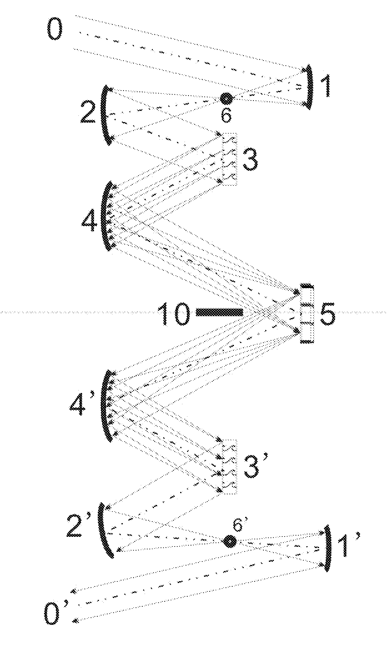
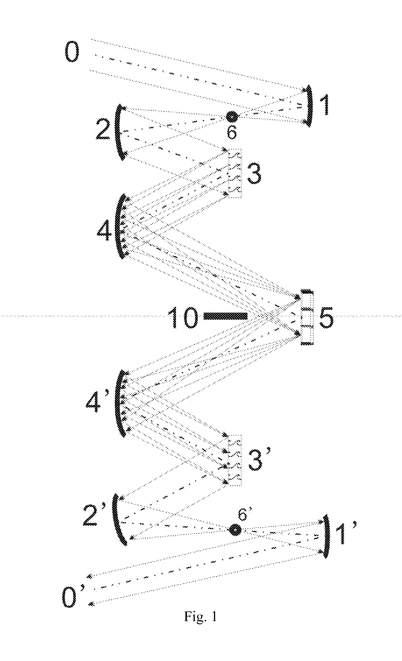
[0071]In this example 1, there are those: the 3 and the 3′ are the reflective planar blazed gratings, which can endure high power laser damage and can be fabricated in a large caliber. The 5 is a multilayer dielectric thin film with micro-structures in it. The 1, the 2, the 4, the 4′, the 2′, and the 1′ are concave reflectors, which are made with strictly eliminating the chromatic aberration, the spherical aberration, and the comatic aberration, to ensure the maximal deviation between the spectrum image plane and the planar reflector for spectrum shaping function design less than the tolerance of the half focal depth deduced from the Rayleigh's Criterion. The 6 and the 6′ are the aperture diaphragm. And the 10 is a slit diaphragm that is composed of a light barrier and its image in the planar reflector for spectrum shaping function design 5. The 0 is the front-end system of CPA and the 0′ is the following amplification stage such as the solid-state amplifier. The 6 is t...

example 2

of the Device

[0078]In this example 2, all the optical element are selected that the parameters of the design requirement and the optical elements are the same as that shown in table 1 in example 1. The spatial arrangement of this spectra shaping device is: all the concave reflectors, the dispersion components, and the aperture in the spectrum decomposing system and those in the spectrum synthesizing system, and all their images are in a vertical planar. That is to say, the spatial arrangement of a spectra shaping device is a spectrum shaping device constructed as a reflective-type vertical imaging construction for the spectroscope system. FIG. 1 schematically illustrates the structure of a spectra shaping device, which the above elements are settled in this optical path construction. The parameters of the spatial arrangement is shown in table 3, which are:

TABLE 3the parameters of the spatial arrangementItemParametersAngle ∠012 between the axis and the centre line of8°the first conca...

example 3

of the Device

[0084]In this example 3, all the optical element are selected that the parameters of the design requirement and the optical elements are the same as that shown in table 1 in example 1. In present invent of device, the spatial arrangement of a spectra shaping device is: all the concave reflectors, the dispersion components, and the aperture in the spectrum decomposing system and those in the spectrum synthesizing system, and all their images are in a horizontal planar. That is to say, the spatial arrangement of a self-collimation CTSI spectrum plane shaping system is a spectrum shaping device constructed as a reflective-type horizontal imaging construction for the spectroscope system, which constructed as vertical symmetric relative to the planar reflector for spectrum shaping function design. FIG. 1 schematically illustrates the structure of a spectra shaping device, which the above elements are settled in this optical path construction. The parameters of the spatial ar...


PUM


Abstract

A spectra shaping apparatus for chirped pulse amplification (CPA): uses a spectrum decomposing system with CTSI construction, a spectrum synthesizing system with CTSI structure that is optically symmetrical to the decomposing structure, and a spectrum shaping system including an aperture and a planar reflector for spectrum shaping function design. The apparatus accomplishes the following functions: firstly decomposing the spectrum of a chirped temporal pulse laser to a spectral domain; then shaping the spectrum in the spectral domain; finally synthesizing un-shiftily this shaped spectrum in the spectral domain into a temporal chirped pulse with a designed shape. The apparatus has the feature of fabricating easy, compacting the structure, requiring less space, and cheap in cost etc., which it can be the different types of configuration for different circumstance application, which it can be not only utilized in a general laser spectrum shaping and spectrum modulation, but also can be utilized for a high energy and ultra-high peak-power laser system in chirped pulse amplification with a large caliber and with a chirped pulse bandwidth of a few nanometers.

Description

PRIORITY CLAIM[0001]The application titled as a spectra shaping device for chirped pulse amplification is the international application, PCT / IB2009 / 050916, filed on 3 May 2009, for entry into the national stage in the United States, where it claims the benefit of the international filing date of the international application designating the United States of America.TECHNICAL FIELD OF THE INVENTION[0002]The present invention relates generally to a pulse shaping device for laser amplification in the power. The invention relates in particular to manipulating the spectral and temporal characteristics of laser pulses, which the spectra shaping device is for a large caliber and high power chirped pulse amplification (CPA) in huge energy, which belongs to the filed of application technology of engineering optics.DISCUSSION OF BACKGROUND ART[0003]In the field of the high-power ultra-short laser pulse amplification, the enhancement of the output of a laser system is hampered by a series of f...

Claims


Application Information

Patent Timeline
IPC IPC(8): G02B27/09
CPCG01J3/1804G01J3/24G01J2003/1282G02B27/0927G02B19/0023G02B27/0983H01S3/005G02B19/0052G02B27/0944
Inventor LI, MINGDAI, YAPINGWANG, TAOZHANG, BIN
Owner LI MING
Why Eureka
Try Eureka