Silk based biophotonic sensors

a biophotonic sensor and micro-silk technology, applied in the field of micro-silk based biophotonic sensors, can solve the problems of inability of light waves to interact with adsorbed or chemically bound analytes present on the surface of these sensors, intrinsic limitations, and the inability of light waves to provide frequency selective responses useful for colorimetric detection

Inactive Publication Date: 2013-12-12
TRUSTEES OF BOSTON UNIV +1
View PDF2 Cites 36 Cited by
  • Summary
  • Abstract
  • Description
  • Claims
  • Application Information

AI Technical Summary

Benefits of technology

[0005]Among other things, the present invention encompasses the recognition that silk-based materials provide a useful component for improved biophotonic sensors, as well as versatile assay platforms that incorporate such biophotonic sensors. In particular, the invention provides biophotonic sensors that incorporate a silk-based material in conjunction with aperiodic nanostructures upon a surface of the sensor. When such a surface is illuminated, the sensor scatters light according to a specific pattern (e.g., a “spectral signature”). The sensor may absorb, reflect, and / or diffract light to create the pattern. The pattern shifts or changes when the surface interacts with an analyte, which brings about local perturbation of light scattering, which forms the basis for the sensing assay system. Because the assay is based on nano-scale photonic sensing and involves a deterministic system (e.g., each surface configuration is associated with predictable “signature” scattering pattern), it allows a flexible means of processing and characterizing samples by a variety of parameters (e.g., multiplexing). The assay platform which incorporates certain aspects of the present invention as described herein is referred to as the “Smart-Slide” platform.

Problems solved by technology

The Bragg scattering process, although providing frequency selective responses that are useful for colorimetric detection, intrinsically has limitations.
For example, the ability of light waves to interact with adsorbed or chemically bound analytes present on the surface of these sensors is limited, since Bragg scattering is a first-order process in surface scattering perturbation theory (Tsang et al., “Scattering of electromagnetic waves,” John Wiley & Sons Inc., New York (2000); Maradudin, “Light scattering and nanoscale surface roughness,” Springer, New York (2007)), and scattered photons easily escape from a periodic surface within well defined spectral bands without prolonged interaction with the sensing layer.

Method used


Image

  • Silk based biophotonic sensors
  • Silk based biophotonic sensors
  • Silk based biophotonic sensors

Examples


example 1

Gratings Fabrication

[0145]Periodic and aperiodic nanoparticle arrays were fabricated using Electron Beam Lithography (EBL) on quartz substrates. The fabrication process flow is as follows: A 180 nm of PMMA 950 (Poly Methyl Meth Acrylate) was spin-coated on top of quartz substrates, and the substrates were soft-baked on a hot plate at 180° C. for 90 sec. A 10 nm-thin continuous gold film was then sputtered on top of the resist to facilitate electron conduction for EBL writing. The nanopatterns were defined using a Zeiss SUPRA™ 40 VP SEM (Zeiss, Oberkochen, Germany) equipped with Raith beam blanker (Raith, Dortmund, Germany) and Nanometer Pattern Generation System (NPGS) for nanopatterning. The resist was subsequently developed and a 40 nm Cr thin film was deposited by e-beam evaporation. After lifting-off using acetone solution, the arrays with Cr nanoparticles were obtained. The resulting features of nanopatterned arrays are shown in FIG. 9 and are approximately 40 nm in height with...

example 2

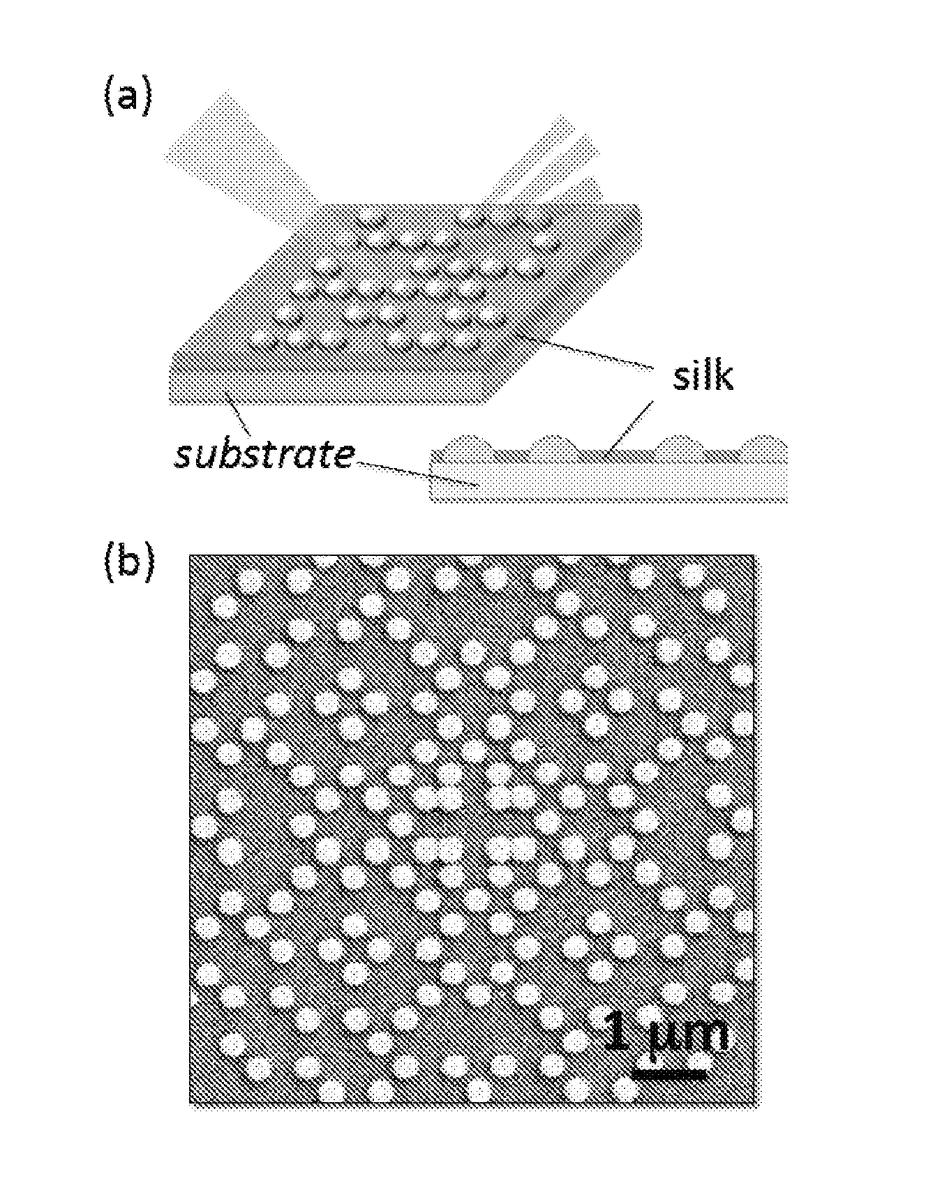
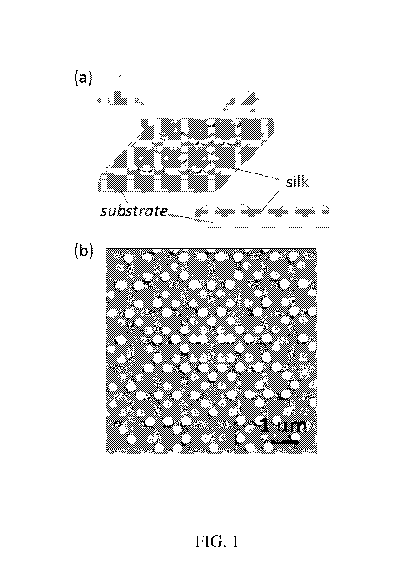
Preparation of Silk Material

[0146]Production of silk fibroin solutions has been described previously. Perry et al., 2008; McCarthy et al., 54 J. Biomed. Mats. Res. 139 (2001). Briefly, sericin, a water-soluble glycoprotein bound to raw fibroin filaments, was removed from the silk strands by boiling B. mori cocoons in a 0.02 M aqueous solution of Na2CO3 for 30-60 min. Thereafter, the remaining silk fibroin bundle was rinsed thoroughly in purified water to extract the glue-like sericin proteins and allowed to dry overnight. The dry fibroin bundle was then dissolved in a 9.3 M aqueous solution of LiBr at room temperature or heated at 60° C., yielding a 20 wt % solution. The LiBr salt was then extracted from the solution over the course of 48 hrs or more, through a water-based dialysis process using Slide-A-Lyzer® 3.5K MWCO dialysis cassettes (Pierce, Rockford, Ill.). Any remaining particulates were removed through centrifugation and syringe-based micro-filtration (5 μm pore size, Milli...

example 3

Dark-Field Scattering Setup and Image Acquisition

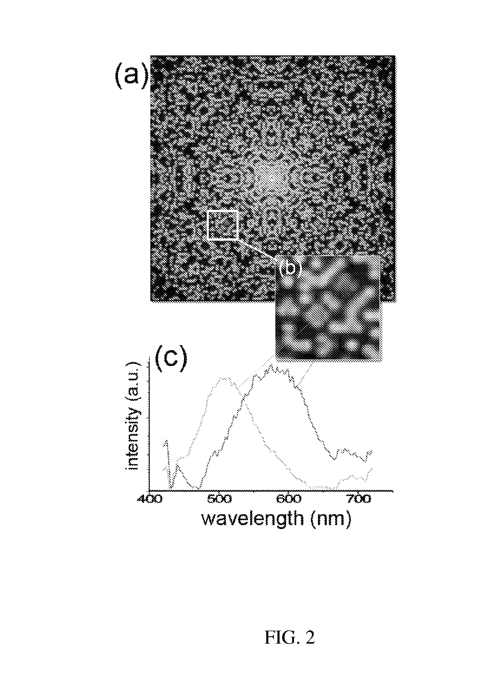
[0150]FIGS. 4B-4D and FIG. 5F were collected in dark-field under white light illumination using a backscattering microscope setup with a 50× objective (N.A.=0.5) and a CCD digital camera (Media Cybernetics Evolution VF). The incident angle of the illumination was approximately 15° to the array plane, as shown in the FIG. 4E. Dark-field images and wavelength spectra were also measured in a transmission configuration using a dark-field condenser with N.A. 0.8-0.92. The transmitted light was collected with a 10× objective through a 1 mm iris (decreasing the N.A. ˜0.1) and spectral images were obtained using a hyperspectreal CCD (CRi Nuance FX) camera coupled to an Olympus IX71 microscope (FIG. 6, FIG. 7, FIG. 8).


PUM

PropertyMeasurementUnit
heightaaaaaaaaaa
radiusaaaaaaaaaa
distanceaaaaaaaaaa

Abstract

The present disclosure relates to biophotonic sensors. An example of a biophotonic sensor may be an apparatus for analyzing a sample. The apparatus may include a substrate, aperiodic nanostructured protrusions disposed on the substrate, and a silk material deposited between the protrusions.

Description

RELATED APPLICATION[0001]This application claims the benefit of U.S. provisional patent application 61 / 369,402, filed Jul. 30, 2010, entitled “Structural Color-Based Sensing in the Visible Regime,” the content of which is incorporated herein by reference in its entirety.GOVERNMENT SUPPORT[0002]This invention was made with government support under grant No. W911NF-07-1-0618 awarded by the Defense Advanced Research Projects Agency (DARPA). The U.S. federal government has certain rights in the invention.BACKGROUND[0003]Conventionally, the detection of features or surface variations on the nanoscale relies on sophisticated instrumentation such as: atomic force or electron microscopy, imaging based on dye-assisted spectroscopic techniques (Bake & Walt, 1 Annu. Rev. Anal. Chem. 515-47 (2008)), or collective resonant effects in plasmonic structures, such as sub-wavelength apertures (Stewart et al., 108 Chem. Rev. 494-521 (2008)), surface enhanced Raman scattering (Stiles et al., 1 Annu. Re...

Claims


Application Information

Patent Timeline
Patent Type & Authority Applications(United States)
IPC IPC(8): G01N21/25
CPCG01N21/25B82Y30/00G01N21/4788G01N33/54373
Inventor OMENETTO, FIORENZOKAPLAN, DAVIDAMSDEN, JASONDAL NEGRO, LUCA
Owner TRUSTEES OF BOSTON UNIV
Why Eureka
Try Eureka