HPLC frit filter assembly

a frit and assembly technology, applied in the direction of electric/magnetic/electromagnetic heating, separation process, instruments, etc., can solve the problems of compromising the filtration function of the frit and its assembly, the need to replace an expensive hplc column, and the difficulty in achieving the goal of maintaining a long life of the separation column, etc., to achieve the effect of higher melting poin

Inactive Publication Date: 2014-01-23
FORD POLYMET +1
View PDF3 Cites 11 Cited by
  • Summary
  • Abstract
  • Description
  • Claims
  • Application Information

AI Technical Summary

Benefits of technology

[0043]A method of making a frit assembly comprises the steps of placing a frit having a selected porosity within a surrounding polymer ring such that a perimeter outer surface of the frit is in contact with an inner perimeter surface of the polymer ring and heating the frit for a predetermined time; where the step of heating the frit is done by induction heating; where the induction heating is done by using a wire having a loop located near the frit, the loop creating a loop having a central axis approximately parallel to the one or more fits being heated and in close proximity thereto; where the induction heating coil is energized with a 400 KHz to 2 Mhz frequency range for approximately 30 to 8 seconds at approximately 2000 W (actual operating parameters depending on the amount of material and its size as understood by persons of ordinary skill in the art); where the step of heating the frit is done by RF heating; where the step of heating is done by infrared heating; wherein the step of heating is done from both ends using a laser light; wherein the step of heating the frit is done from both ends using contact heating; wherein an anvil (made of a non-inductively (non-metallic) heatable material with a higher melting point than the polymer ring that it supports) supports the frit and surrounding polymer ring during heating; wherein a lower anvil supports the frit and surrounding ring and an upper anvil covers the frit and surrounding polymer ring during heating; wherein the surfaces facing the frit are polished; wherein the anvils are cooled by using cooling air or by using a water jacket; wherein a seal created between the frit and surrounding polymer ring is checked using a water flow through the frit and surrounding ring assembly; where a seal created between surrounding polymer ring is checked using an air flow through the frit and surrounding ring assembly; where the step of placing frit within a surrounding polymer ring is done on a support anvil; wherein the step of placing the frit within the surrounding polymer ring includes placing a cover anvil over the frit and surrounding polymer ring's wherein the surfaces of the anvils facing the frit are polished.
[0044]A frit assembly comprising, a frit having a first side and the second side opposite the first side and a perimeter side extending around the frit and between the first side and the second side wherein pore openings in the frit prevent passage of particles larger than a size of the openings in the frit as fluid flows through the frit from the first side to second side; where the frit has a set of perimeter pore openings on its perimeter side, the frit support ring has a frit facing surface surrounding and in interlocking contact with the perimeter side of the frit, where the material frit facing surface has migrated into and at least partially through the perimeter pore openings all around the perimeter side of the frit providing mechanical engagement and adhesion between the frit and the frit support ring where the mechanical engagement and adhesion between the frit and frit support ring is characterized by cutting the assembly in half along the central axis of the flow passage through the frit and determining that each half of the frit remains adhered to its frit support ring on its perimeter side. Which is in contrast to a frit filter assembly where the mechanical engagement and adhesion between the frit and the frits support ring fails, causing the frit and its perimeter side frit support ring to separate upon cutting the assembly in half.

Problems solved by technology

Achieving these goals while maintaining a long separation column lifespan has been difficult to achieve.
This difficulty is most evident and acute in diagnostic fields (automated biomedical machines) where frit prefilter failure can result in the need to replace an expensive HPLC column.
Each of these three methods has disadvantages, which can compromise the filtration function of the frit and its assembly.
These failure methods may lead to the contamination of the separation column.
Insert molding a sealing ring around the frit can create bonding issues between the frit and the surrounding (injection molded) plastic or polymer.
In addition, the injection molded plastic can flow over the surface of the frit unobstructed and create a solid plastic barrier (or obstruction) to fluid flow through the frit.
Such blockage of flow can cause the product of such a process to be rejected as unusable.
Lastly, the press fitting (interference fit) of a frit into a surrounding plastic ring is problematic in that the frit has minimal structural rigidity.
A compressive stress at its perimeter will result in a localized deflection and cracking to accommodate the interference fit with the surrounding plastic (polymer) ring.
Particles entering the LC system may lead to: A) clogging of capillaries, interference with the chromatography by changing chromatographic parameters, or B) disturbance of the detection function.
Although the porosity may be within specification, it is unlikely that this frit would provide adequate flow.
Moving parts within the HPLC system can generate debris.
Despite the superior sealing materials available today, small irregularities in the seal itself or the piston, dirt on the piston or an improperly installed seal will result in small particles being removed from seal and being washed downstream towards the injection valve.
Improper valve operation can occur as a result of debris interfering with proper sealing of the valve.
Alternatively, debris entering the valve can destroy the sealing surfaces, generating additional particles and making it necessary to repair the valve or replace the rotor seal.
Particles entering with the sample, or those generated by the injection valve, can easily clog the separation column.
Debris passing through capillary inlet tubing will collect in the separation column and can also affect the separation column performance.
Any debris that enters the column inlet will be trapped on the inlet filter.
Even though the frit can eventually become clogged, the expensive column bed will remain intact.
If a frit with a very small porosity is chosen, the small particles contained or generated by the packing material will eventually work themselves into the pores and clog the frit, resulting in an increased back pressure.
The use of large volume filtering devices between the column outlet and the detector can result in band broadening.
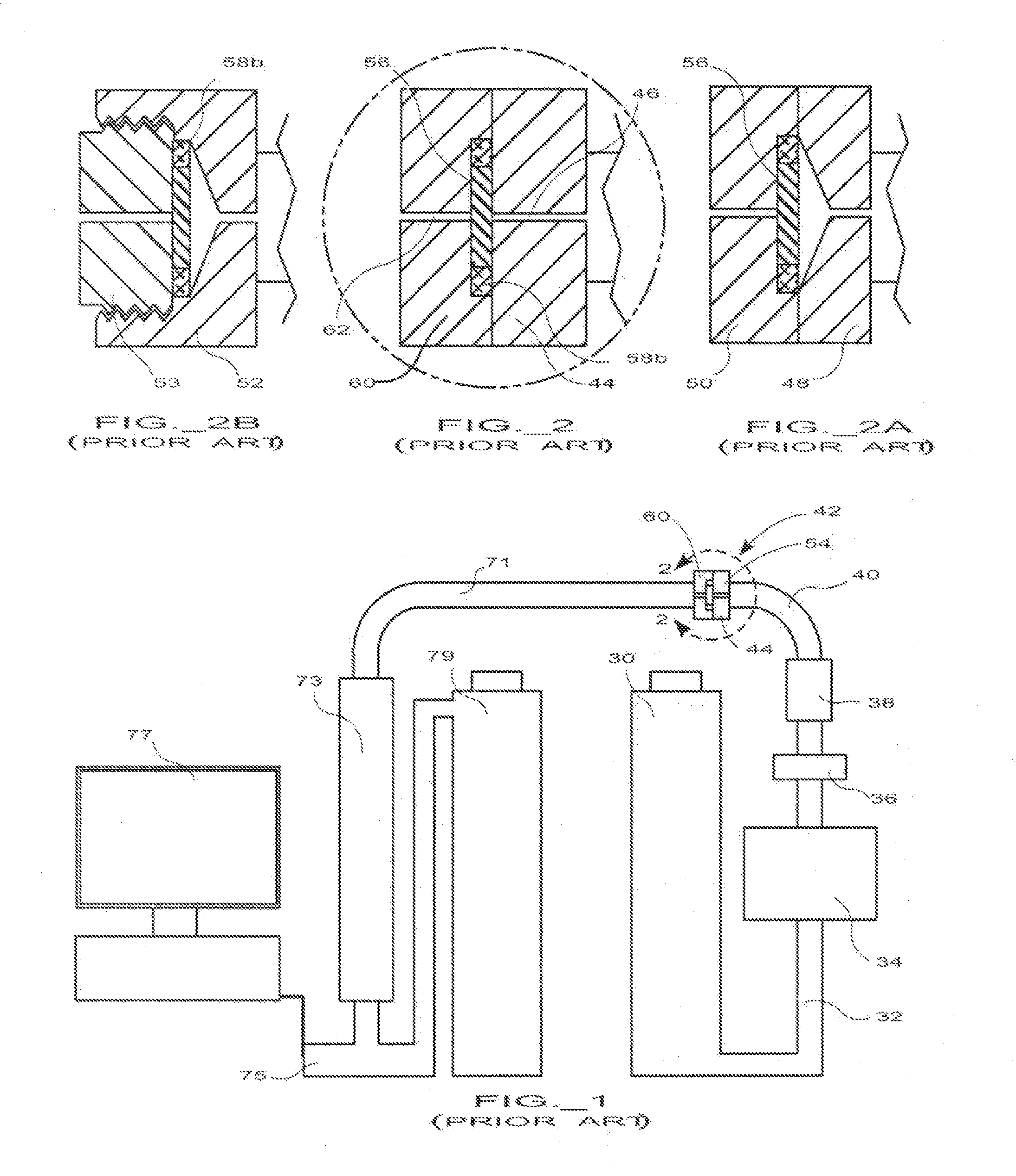
First, since a stainless steel frit will not seal well against a stainless fitting, the ring acts as a gasket.
Soldering, either hard or soft, and brazing are not recommended with porous metal powder metallurgy parts because the porous matrix metal tends to “wick” (soak up) the flux and solder due to capillary action.
The application of epoxies is also an issue, if applied before items are mated the epoxy material will shear / wipe away as it is inserted.
In practice liquid epoxy flows through the available space and fills all voids, while high viscosity epoxies do not flow to achieve more than superficial bonding.
Attempts at epoxy bonding have not achieved satisfactory process control nor sealing of frits.
(Further the resident nature of epoxy material is such that it is nearly impossible to bond with thermoplastic materials such as Delrin®.
Appearances can be deceiving.
Further, insert molding requires very tight process controls of: overmold temperature, plastic temperature, pressure, hold time, and frit temperature.
The temperature of the frit in an injection (or insert) mold is hard to control since it relies on generally conductive heat transfer (surface contact with mold) to both hold and control temperature.
To achieve an acceptable frit temperature control using contact heat transfer, frit dimensions have to be specified and manufactured in a narrow thickness tolerance, thereby increasing the manufacturing complexity and cost associated with producing a frit filter assembly.
A further disadvantage of this thermal process is that as fits have porous open spaces (occupied by a gas such as air during the molding process) the bulk material of the frit tends to be a poor thermal conductor (for the thermal energy generated by the surrounding mold cavity), thereby further compounding the problem of achieving and maintaining a uniform temperature throughout the bulk material of the frit.
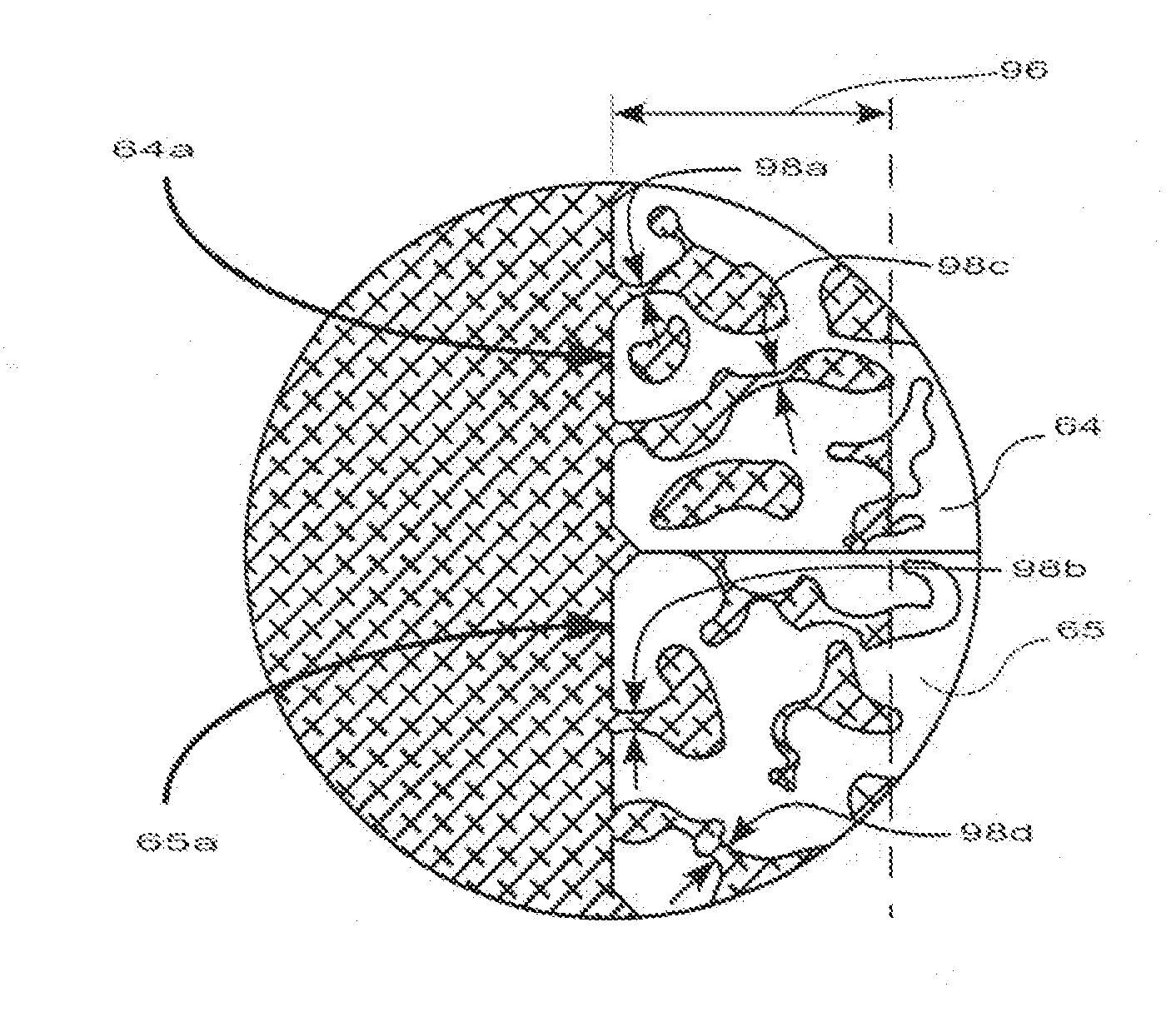
This failure mode is considered a blow by or filter failure.
The filter failure results in contaminants from upstream of the frit of being allowed to flow downstream and begin to contaminate the expensive HPLC separation column.

Method used


Image

  • HPLC frit filter assembly
  • HPLC frit filter assembly
  • HPLC frit filter assembly

Examples


Embodiment Construction

[0069]A HPLC system includes a solvent tank 30 having solvent flowing through a pipe 32 to a pump 34 which in turn pressurizes and drives solvent through a solvent filter 36 to an injection valve 38 where sample materials or other products to be analyzed are injected. The material is then driven through the piping (tubing) 40 to a stainless steel frit holder or prefilter assembly 42 containing a frit holder inlet fitting assembly 44, a stainless steel filter assembly 54, and a frit holder outlet fitting assembly 60. The filtered fluid once having passed through the frit filter in the prefilter assembly 42 passes through the piping 71 to analysis column 73, where as described above, the constituents move according to their analyte to a detector 75. A recorder / personal computer (PC) 77 receives analysis signals from the detector and the fluid coming out of the separation column is passed into a waste reservoir 79.

[0070]Alternate arrangements of prior art prefilter assemblies 42 are sh...


PUM


Abstract

An apparatus and method for creating a high pressure chromatography frit filter assembly is described. The frit is positioned in bondable contact with a polymer ring and then the frit is subject to inductive or targeted heating to cause the frit material to heat the adjacent polymer ring from the inside out. The polymer to liquefies and flow into and past one or more narrowing locations in the pore passageway extending from the surface of the frit to an infusion depth, which provides previously unachieved secure mechanical engagement and adherence and resistance to pressure blow by (break through) and prevents the flow of contaminants between the edge of the frit and the facing edge of the polymer ring in a high pressure or ultra-high pressure chromatography system, where inlet pressures in the range of pressures up to 18,000 PSI are expected.

Description

Field of the Invention[0001]High-pressure liquid chromatography (HPLC) is used in analytical and biological chemistry to separate chemical compounds in mixtures for analysis or purification. This disclosure concerns filter assemblies for use in high-pressure small volume systems, e.g., UHPLC (ultrahigh pressure chromatography) systems.BACKGROUND OF THE INVENTION[0002]High-pressure liquid chromatography (HPLC) is used in analytical chemistry and biochemistry to separate chemical compounds in mixtures for analysis, purification, and other uses.[0003]Components in a mixture are separated on a column packed with silica-based particles (the stationary phase) by pumping a solvent (the mobile phase) through the column. Depending on the unique affinity of each component (the analyte) between the mobile phase and the stationary phase, each analyte migrates along the column at a different rate and emerges from the column at a different time, thus establishing separation of the mixture. Analyt...

Claims


Application Information

Patent Timeline
Patent Type & Authority Applications(United States)
IPC IPC(8): B01D15/10H05B6/22
CPCG01N30/6026G01N30/603H05B6/10
Inventor FORD, ROBERT A.CHIN, VANCE R.MEDLOCK, KEVIN A.KEEGAN, MICHAEL P.
Owner FORD POLYMET
Why Eureka
Try Eureka