
Multi-Stage Circulating Fluidized Bed Syngas Cooling

a fluidized bed and fluidized cooling technology, applied in the direction of indirect heat exchangers, combustible gas production, lighting and heating apparatus, etc., can solve the problems of increasing the overall cost of cooling syngas, sacrificing process efficiency, and protecting relatively expensive heat transfer surfaces. , to achieve the effect of lightening density

Active Publication Date: 2014-02-27
THE SOUTHERN CO
View PDF11 Cites 11 Cited by
  • Summary
  • Abstract
  • Description
  • Claims
  • Application Information

AI Technical Summary

Benefits of technology

The present patent describes a multi-stage syngas cooler for cooling high temperature syngas from a coal gasifier. The cooler includes a dense fluid bed with imbedded cooling coils in communication with a hot syngas inlet stream. The syngas cooler can have multiple stages and a cyclone to disengage syngas and solids. The hot syngas flows through the cooler and exchanges heat with the circulating cooler solids. This cooler design helps to minimize deposition problems and fouling materials in the syngas. The technical effect of the present invention is to provide a more efficient and reliable cooling system for high temperature syngas from a coal gasifier.

Problems solved by technology

For those of skill in the art of syngas cooling, difficulties of cooling syngas when directly contacting syngas with the heat transfer surfaces are well-known, and include: plugging the gas flow path due to entrained substances in the syngas, fouling of the heat transfer surfaces due both to deposition of fine molten ash droplets and to tar components in the syngas, erosion due to fine ash and char entrained from the gasifier, and corrosion due to components in the syngas such as hydrogen sulfide and chloride.
Another difficulty associated with syngas cooling is identifying and handling materials of construction for heat transfer surfaces that are compatible with high temperatures and protecting relatively expensive heat transfer surfaces for reliable operation.
At present, options attempting to circumvent the many difficulties of reliably cooling syngas greatly sacrifice process efficiencies.
Such quench cooling systems involve an expensive radiant syngas cooler and less-than-reliable water treatment systems to separate particles and treat water as the spent quench water, which is highly corrosive and erosive in nature, increasing overall costs to cool the syngas.
In addition, practical experience indicates that the combination of radiant and quench cooling of syngas is not completely effective in limiting (avoiding) plugging problems of a downstream convective cooler.
Even then, a syngas cooler to cool the syngas exiting such gasifiers is a relatively expensive piece of equipment due to the use of exotic alloys for the cooling tubes.
In a conventional convective cooler that contact the syngas near 1000° C. under high pressure conditions such exotic and expensive alloys must be used.
A further difficulty in cooling the syngas from fluidized bed gasifiers is the fine ash and char particles entrained therein that tend to erode the cooling tube surfaces.
Deposition and fouling gradually degrades the cooling effectiveness and results in less than desirable superheated steam conditions, affecting generation capacity in an integrated gasification combined cycle (IGCC) plant.
Syngas coolers have limited cooling capacities due to internal hydrodynamics, pressure drop and other process considerations that limit its physical dimensions.
Multiple, parallel syngas coolers in a process line inevitably increase both the costs and layout complexities in handling high pressure syngas near 1000° C.
Processing biomass and bituminous coals in some fluidized bed gasifiers lead to tar formation that entrains with the syngas as it exits the gasifier.
The tar components deposit on syngas cooler heat transfer surfaces and downstream equipment and the deteriorating foul conditions eventually lead to an inoperable process.
Similar difficulties are encountered while processing coals that contain higher percentage of alkali metals in coal minerals.
Even at increased costs and overall decreases in process efficiencies, conventional syngas coolers still cannot be reliably used for these processes with known mitigating measures upstream.
Yet the '848 two-stage fluidized bed cooling system encounters practical difficulties.
One notable disadvantage relates to the substantial amount of oily matter contained in the syngas exiting the cooler that makes it difficult and expensive to treat the sour water that is generated from scrubbing the syngas downstream.
Another serious issue is safety—as disclosed, the operating temperature of the second-stage cooler is substantially below the auto ignition temperatures of major components of the syngas such as carbon monoxide (609° C.
Beyond such safety concerns, the low temperature partial oxidation method necessitates a much larger space for the cooler for a combustion zone and generates much more CO2 than CO.
The cooling capacity of the '848 cooler is also disadvantageous.
Yet parallel cooler arrangements are expensive because the syngas has to be routed to the coolers by refractory lined pipes.
Yes this teaching oversimplifies a complicated issue.
When the cooling surface is in the direct flow path of the riser, where gas superficial velocity is typically above 5 m / s, the erosion of even a cooler cooling surface is inevitable.
It is therefore impractical to install the cooling surface inside the riser.
Although the teaching in this Publication can have wide applications for treating syngas, it too does not disclose how to avoid contaminant accumulations on the particle surfaces and regeneration of bed materials from such contaminants.
Furthermore, the Publication discloses a single-stage cooler that does not address the steam conditions necessary for power generation.

Method used


Image

  • Multi-Stage Circulating Fluidized Bed Syngas Cooling
  • Multi-Stage Circulating Fluidized Bed Syngas Cooling
  • Multi-Stage Circulating Fluidized Bed Syngas Cooling

Examples


Embodiment Construction

[0056]To facilitate an understanding of the principles and features of the various embodiments of the invention, various illustrative embodiments are explained below. Although exemplary embodiments of the invention are explained in detail, it is to be understood that other embodiments are contemplated. Accordingly, it is not intended that the invention is limited in its scope to the details of construction and arrangement of components set forth in the following description or illustrated in the drawings. The invention is capable of other embodiments and of being practiced or carried out in various ways. Also, in describing the exemplary embodiments, specific terminology will be resorted to for the sake of clarity.

[0057]It must also be noted that, as used in the specification and the appended claims, the singular forms “a,”“an” and “the” include plural references unless the context clearly dictates otherwise. For example, reference to a component is intended also to include composit...


PUM


Abstract

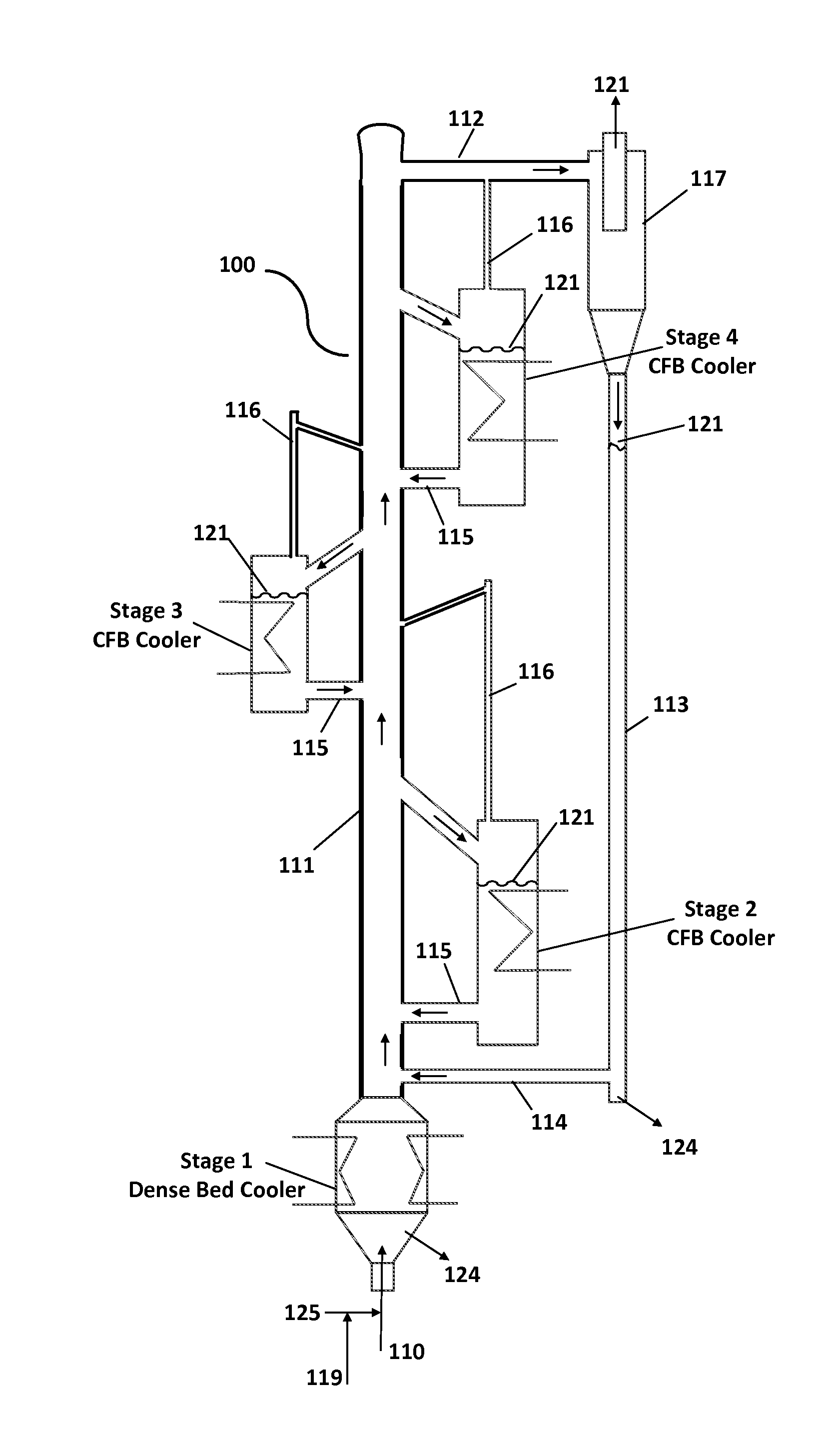
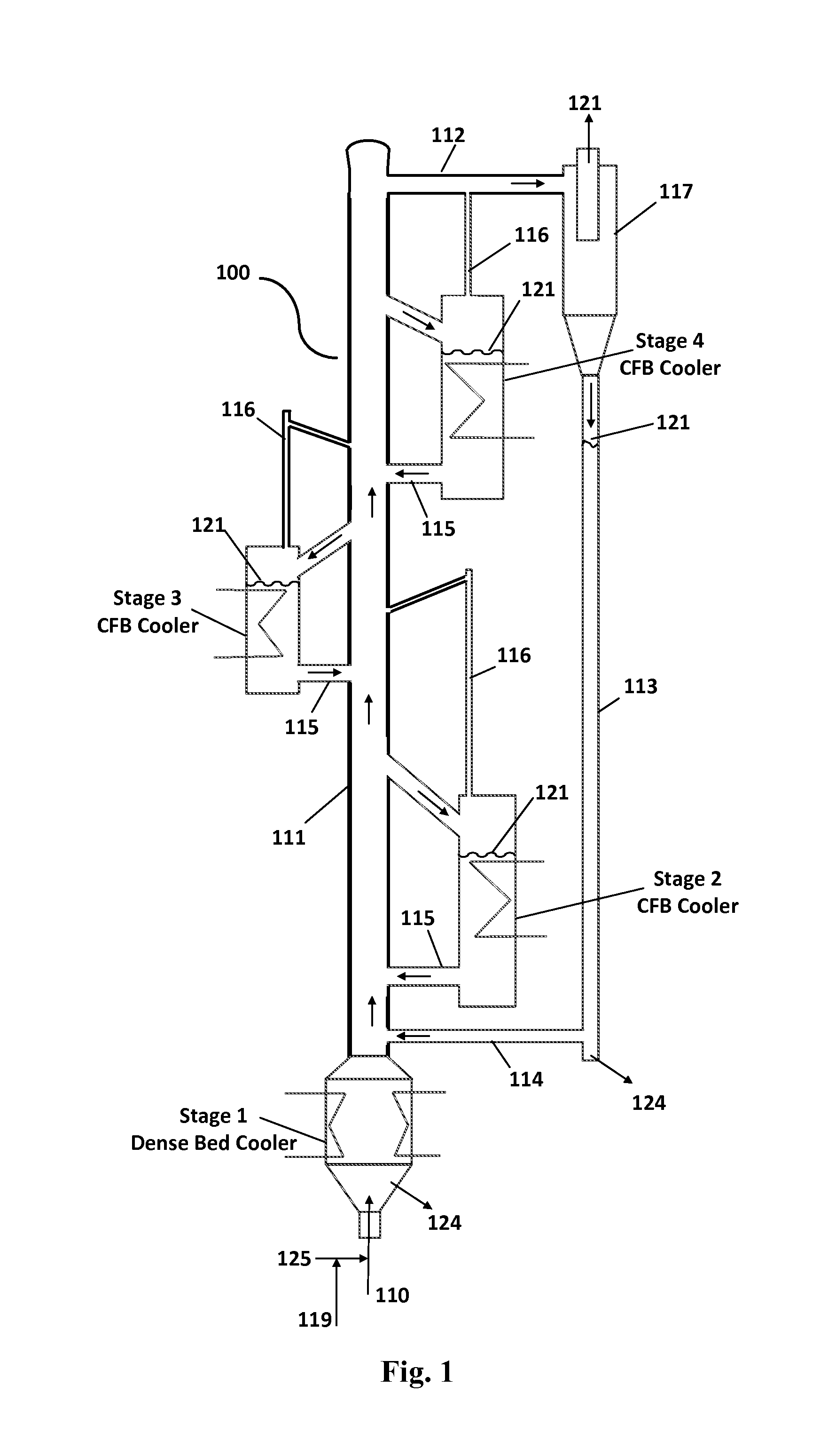
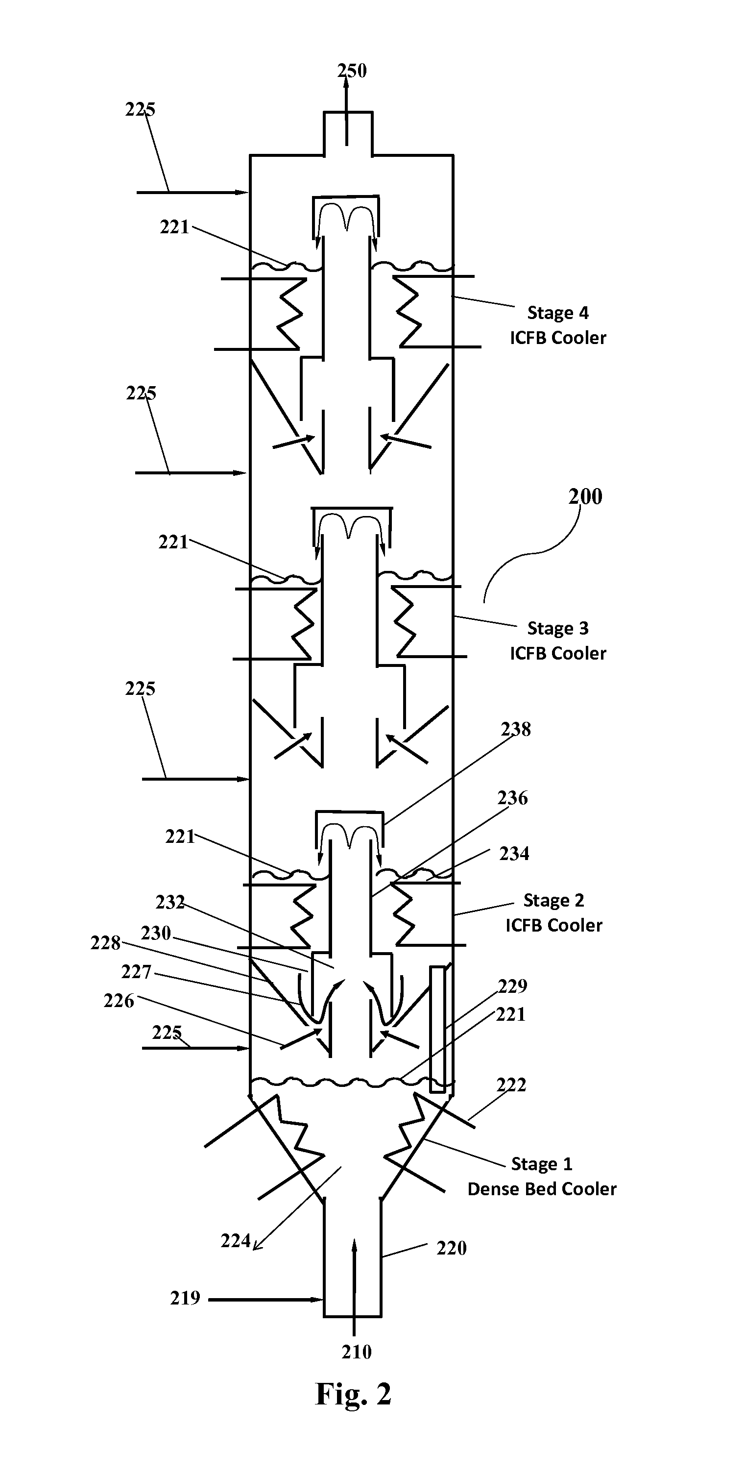
A method and apparatus for cooling hot gas streams in the temperature range 800° C. to 1600° C. using multi-stage circulating fluid bed (CFB) coolers is disclosed. The invention relates to cooling the hot syngas from coal gasifiers in which the hot syngas entrains substances that foul, erode and corrode heat transfer surfaces upon contact in conventional coolers. The hot syngas is cooled by extracting and indirectly transferring heat to heat transfer surfaces with circulating inert solid particles in CFB syngas coolers. The CFB syngas coolers are staged to facilitate generation of steam at multiple conditions and hot boiler feed water that are necessary for power generation in an IGCC process. The multi-stage syngas cooler can include internally circulating fluid bed coolers, externally circulating fluid bed coolers and hybrid coolers that incorporate features of both internally and externally circulating fluid bed coolers. Higher process efficiencies can be realized as the invention can handle hot syngas from various types of gasifiers without the need for a less efficient precooling step.

Description

CROSS-REFERENCE TO RELATED APPLICATIONS[0001]This application claims the benefit under 35 U.S.C. §119(e) of U.S. Provisional Application No. 61 / 693,707, filed 27 Aug. 2012, which is incorporated by reference in its entirety.STATEMENT REGARDING FEDERALLY SPONSORED RESEARCH OR DEVELOPMENT[0002]This invention was made with Government support under Agreement / Contract Number DE-NT0000749, awarded by the United States Department of Energy. The Government has certain rights in the invention.BACKGROUND OF THE INVENTION[0003]1. Field of Invention[0004]The invention relates to a multi-stage circulating fluidized bed (CFB) cooler for cooling a hot gas stream from a reactor while generating both saturated steam and superheated steam. More specifically, the invention is associated with a cooler for cooling the hot syngas from a gasifier handling carbonaceous materials such as coal, biomass or municipal wastes as feed, the cooler simultaneously generates high pressure saturated and superheated st...

Claims


Application Information

Patent Timeline
Patent Type & Authority Applications(United States)
IPC IPC(8): F28D15/00
CPCF28D15/00C10J3/86C10K3/005C10J2300/093C10J2300/1884C10J2300/1892Y02E20/16F28D2021/0075F28D13/00Y02E20/18F28D21/0001
Inventor LIU, GUOHAIVIMALCHAND, PANNALALGUAN, XIAOFENGPENG, WANWANG
Owner THE SOUTHERN CO
Learn More