Graphene-based composite materials, method of manufacture and applications thereof

Inactive Publication Date: 2014-04-10
SAUDI BASIC IND CORP SA
View PDF7 Cites 60 Cited by
  • Summary
  • Abstract
  • Description
  • Claims
  • Application Information

AI Technical Summary

Benefits of technology

[0007]The composite material can be prepared by contacting a hydrazine-reduced graphene oxide with a relaxor ferroelectric material in the presence of a

Problems solved by technology

Unfortunately, the dielectric permittivity of polymer materials is typically less than desirable; and in order to realize the potentials of polymer materials, it is necessary to substantially improve their dielectric permittivity.
However, the improvement on dielectric permittivity is limited even with high filler loadings.
In addition, the mechanical properties of the polymer materials such as flexibility can be compromised

Method used


Image

  • Graphene-based composite materials, method of manufacture and applications thereof
  • Graphene-based composite materials, method of manufacture and applications thereof
  • Graphene-based composite materials, method of manufacture and applications thereof

Examples


example 1

[0069]A hydrazine monohydrate reduced graphene oxide / P(VDF-TrFE-CFE) composite material was prepared as follows.

[0070]Graphene oxide was prepared from natural graphite according to a modified Hummer's method as described by Park. S. et al. in Chemical Materials, volume 20, pp. 6592-4 (2008). For example, 75 ml of concentrated sulfuric acid was added to 1.5 g of graphite powder and 1.5 g of sodium nitrate in the beaker and stirred for 15 min at room temperature before the beaker was kept in an ice bath. Then 9 g of potassium permanganate was added slowly into the mixture and kept in the ice bath for 30 min. After the ice bath was removed, the reaction was continued for 48 hours under stirring at room temperature. The brown slurry or thick paste was then added into 138 ml of deionized (DI) water and the brown suspension was stirred for 10 min Next, 420 ml of warm water was added followed by a slow addition of 30 ml of hydrogen peroxide to provide a yellow suspension. The suspension wa...

example 2

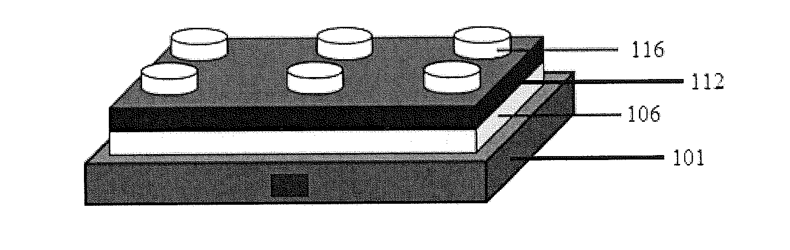
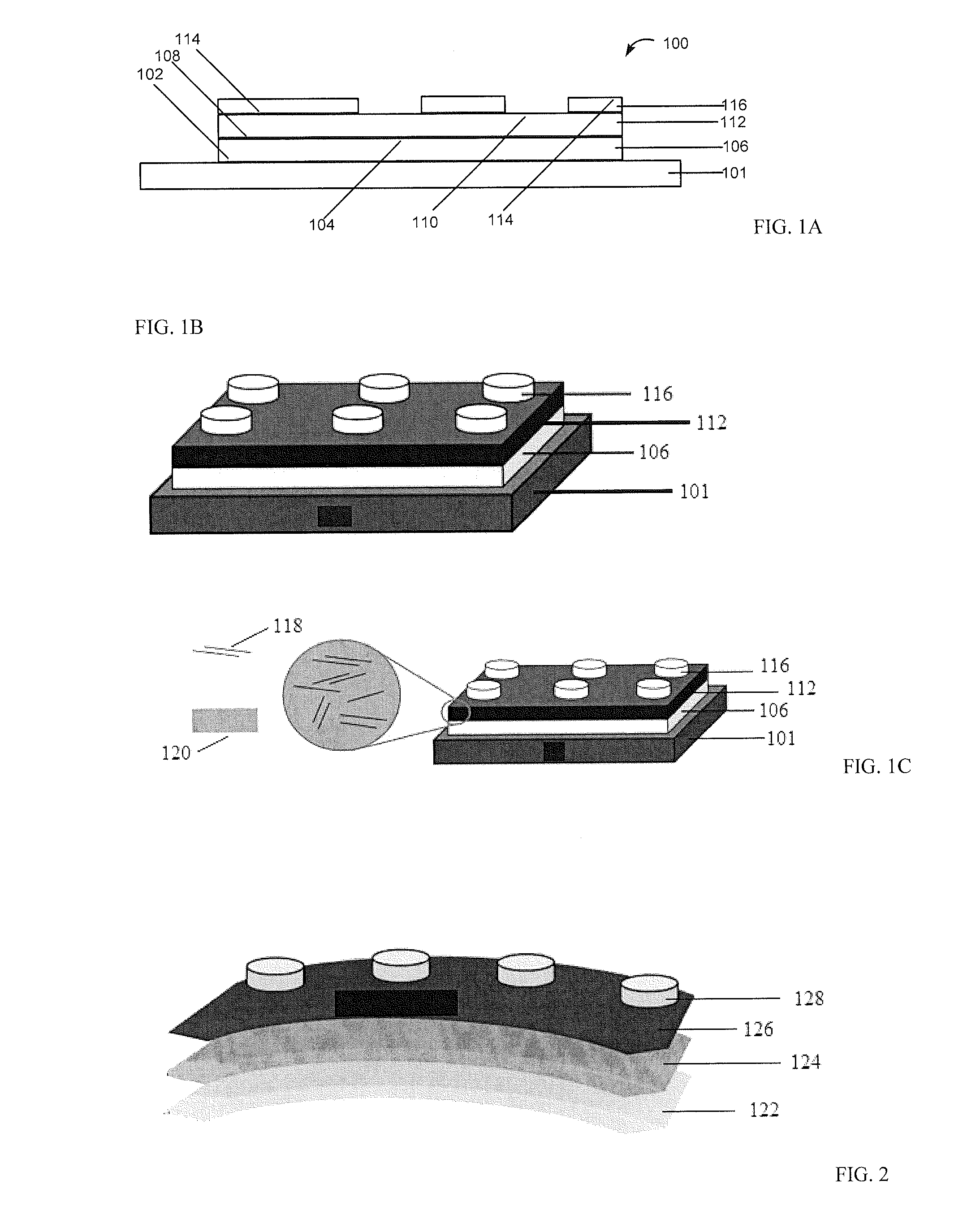
[0074]With reference to FIGS. 1A, 1B, and 1C, a capacitor device 100 was fabricated on a platinum coated silicon substrate 101 having a dielectric thin film 112 between the platinum 106 and aluminum electrode 116.

[0075]Platinum coated silicon substrates were cleaned with acetone, isopropanol and deionized water. HZ-rGO / P(VDF-TrFE-CFE) composite material in DMF was drop-cast directly onto platinum. The cast film was left to dry overnight in air. Air-dried films were transferred into a vacuum oven and dried at 70° C. for 48 h. Top aluminum electrodes were thermally evaporated and patterned on the top surface of the films using a shadow-mask

example 3

[0076]Capacitors can be fabricated using different substrates and / or electrodes. All-organic capacitor devices can be fabricated on high performance polyetherimide substrates such as SABIC ULTEM® 1000B. Given the low temperature processing of the composite materials of this disclosure, fabrication can also be extended to other substrates such as PET and LEXAN®. These flexible substrates are coated with a thin layer of highly conducting polymer(poly(3,4-ethylenedioxythiophene):poly(styrene sulfonic acid), PEDOT:PSS Clevios PH-1000 (Heraeus) doped with ˜4% Dimethylsulfoxide (DMSO)), serving as a bottom electrode. Top electrodes are patterned via inkjet printing of doped PH1000. FIG. 3 illustrates a capacitor device fabricated on a flexible substrate having a thin film dielectric between two highly conducting doped PEDOT:PSS electrodes, wherein the dielectric thin film comprises the composite materials of this disclosure, for example HZ-rGO / P(VDF-TrFE-CFE).


PUM

PropertyMeasurementUnit
Thicknessaaaaaaaaaa
Thicknessaaaaaaaaaa
Dielectric polarization enthalpyaaaaaaaaaa

Abstract

Disclosed herein is a composite material comprising a relaxor ferroelectric material and a hydrazine-reduced graphene oxide, wherein the weight ratio of the composite material to the hydrazine-reduced graphene oxide is 9:1 to 200:1. The composite materials have high dielectric permittivity and low dielectric losses and can be used to manufacture various high dielectric permittivity components.

Description

CROSS-REFERENCE TO RELATED APPLICATION[0001]This application claims the benefit of U.S. Provisional Application No. 61 / 711,279 filed Oct. 9, 2012, which is hereby incorporated by reference in its entirety.BACKGROUND OF THE INVENTION[0002]This disclosure relates generally to graphene-based composite materials, and more particularly, to reduced graphene oxide composite materials and their methods of manufacture. This disclosure also relates to the application of the composite materials in electronic devices.[0003]Polymeric materials have great potential for application in electric capacitors, piezoelectric devices, optical modulators, storage media, memory devices, and the like. Unfortunately, the dielectric permittivity of polymer materials is typically less than desirable; and in order to realize the potentials of polymer materials, it is necessary to substantially improve their dielectric permittivity.[0004]One way to improve the dielectric permittivity of polymer materials is to i...

Claims


Application Information

Patent Timeline
IPC IPC(8): H01G4/14
CPCH01G4/14C08K3/04Y10S977/779C08L101/00C08K9/02C08L2203/20C08L2666/55
Inventor ALMADHOUN, MAHMOUD N.ALSHAREEF, HUSAM N.BHANSALI, UNNAT S.XAVIER, PRINCEODEH, IHAB N.
Owner SAUDI BASIC IND CORP SA
Why Eureka
Try Eureka