
Collection and Concentration System for Biologic Substance of Interest and Use Thereof

a technology of biological substances and concentration systems, applied in the field of systems and devices for collecting and concentrating biologic substances of interest, can solve the problems of large equipment requirements, difficult and technical challenges to detect, isolate, and collect rare cell detection ctcs, and the major bottleneck of most systems for rare cell detection lies in imaging techniques,

Active Publication Date: 2014-05-01
ACAD SINIC
View PDF9 Cites 23 Cited by
  • Summary
  • Abstract
  • Description
  • Claims
  • Application Information

AI Technical Summary

Benefits of technology

This patent is about a system, method, and device related to collecting and concentrating target biologics from biologic samples, such as rare cells and proteins, for various microfluidic applications. The system includes a sample inlet, collection device, concentration device, and sample outlet. The method involves capturing and releasing the target biologic from the collection device, increasing its concentration, and optionally discarding unwanted components or confining it to a concentration region. The concentration can be achieved by culturing the target biologic or performing various assays. The technical effect of this patent is to provide a reliable and efficient method for collecting and concentrating target biologics for microfluidic applications.

Problems solved by technology
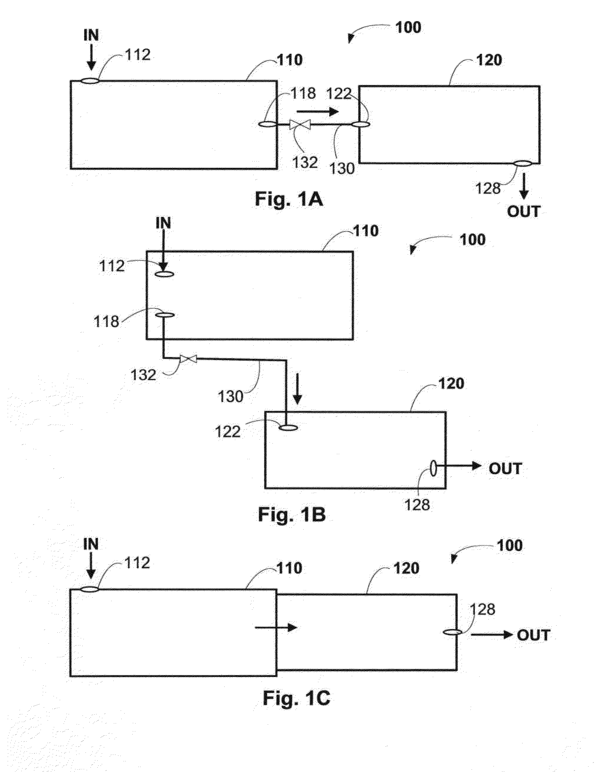
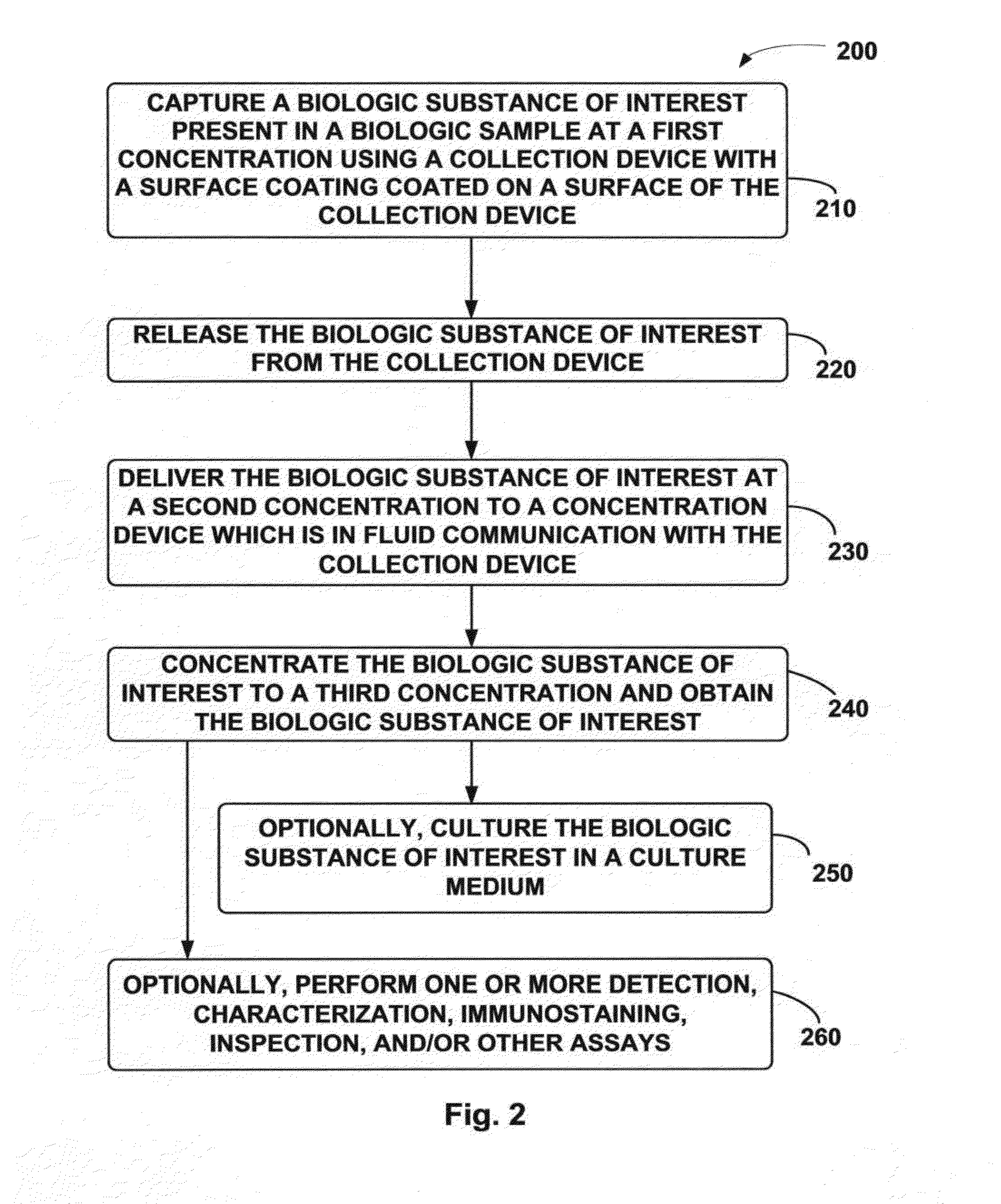
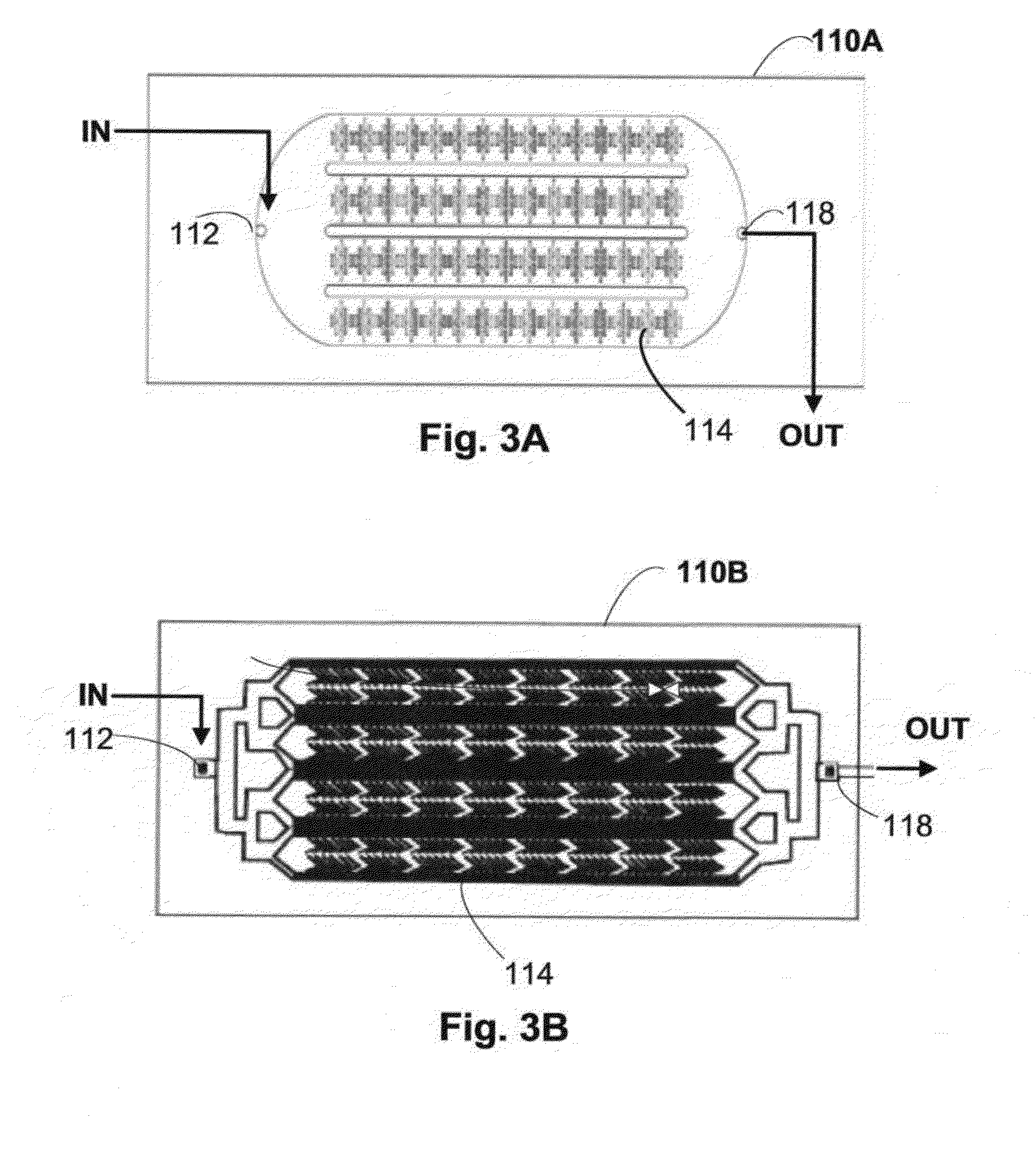
However, for most cancers, the corresponding circulating tumor cells (CTCs) shed in blood are very scarce, making it very difficult and technically challenging to detect, isolate, and collect these CTCs.
Furthermore, major bottleneck of most systems for rare cell detection lies in imaging techniques after targeted biologics of interest (e.g., rare cells or CTCs) are collected.
Most immunomagnetic systems and microfluidic platforms for collecting target proteins or cells require bulky and expensive equipment, such as automated staging microscopes, automated scanners (e.g., for scanning and autofocusing in microfluidic channels) and / or readers (e.g., for quantitating scanned images).
Moreover, a minimum of several hours of labor-intensive manual inspection of collected biological samples and / or images by a trained specialist may still be required.

Method used


Image

  • Collection and Concentration System for Biologic Substance of Interest and Use Thereof
  • Collection and Concentration System for Biologic Substance of Interest and Use Thereof
  • Collection and Concentration System for Biologic Substance of Interest and Use Thereof

Examples


example 1

Preparation of the Two-Layer Surface Coating

[0109]Preparation of the Nonfouling Composition:

[0110]Supported lipid bilayer (SLB) was prepared by dissolving POPC and b-PE (commercially available from Avanti Polar Lipids, USA) in chloroform, in a clean glass tube at a final lipid concentration of 5 mg / mL. The POPC / b-PE solution was dried by vortexing under a slow stream of nitrogen to form a thin, uniform POPC / b-PE film. The POPC / b-PE film was dried in a vacuum chamber overnight to remove residual chloroform. The dried POPC / biotin-PE film was dispersed in and mixed with a phosphate buffer containing 10 mM of phosphate buffered saline, 150 mM of sodium chloride aqueous solution, and 0.02 (w / v) of sodium azide (NaN3, commercially available from Sigma-Aldrich, USA), with the pH adjusted to 7.2. The mixed solution was filtered through 100-nm, followed by 50-nm Nuclepore® track-etched polycarbonate membranes (Whatman Schleicher & Schuell, Germany) for at least 10 times under 150 psi at room...

example 2

Preparation of a Microfluidic Chip

[0124]The microfluidic chip can be prepared by using a commercial CO2 laser scriber (Helix 24, Epilog, USA) to engrave the microtrenches to form microstructures on the PMMA substrate. The microfluidic chip, nuts, PMMA substrate and glass slides were cleaned with MeOH, detergent and water, followed by 10 min sonication. The nuts and the solid substrates were dried by nitrogen gas and baked for 10 min at 60° C. The PMMA substrate was bonded with nuts by chloroform treatment. The PMMA substrate and the glass slide were joined together using an adhesive (e.g. 3M tape from 3M, USA). The assembled chip was scraped by a plastic tip to tighten the bonded components.

example 3

CTCs Binding to the Surface Coating

[0125]A total of 8 Blood samples were used to determine the CTC capture efficiency of the surface coating in the microfluidic chip in Example 2. Each blood sample contained 2 ml of blood samples from stage IV colon cancer patients and the sample was introduced to the sealed channel of the microfluidic chip at 0.5 ml / hr, controlled by a syringe pump. Subsequently, the sealed channel in the microfluidic chip was rinsed with 0.5 ml of PBS buffer at the flow rate of 1 ml / h, followed by in situ immunostaining.

[0126]The surface coating before and after the buffer rinse are compared. Prior to the buffer rinse, the surface coating was covered with non-specific blood cells (low-level red fluorescence in upper left) and four CTCs (red dots in lower left). After the buffer rinse, almost all of the non-specific blood cells were removed (upper right) but the four CTCs (lower right) remained on the surface coating. The number of CTCs captured per ml of blood for...


PUM

PropertyMeasurementUnit
Surface areaaaaaaaaaaa
Concentrationaaaaaaaaaa
Microstructureaaaaaaaaaa

Abstract

A system and method thereof for collecting and concentrating a biologic substance of interest is provided. The biologic of interest obtained from a biologic sample present at an initial low concentration (or low number counts) can be captured and released through a collection device of the system to an intermediate second concentration, and further recovered through a concentration device of the system to a third concentration, thereby facilitating subsequent detection, characterization, enumeration, immunostaining, inspection, imaging, culturing, molecular analysis, and / or other assays.

Description

CROSS-REFERENCE TO RELATED APPLICATIONS[0001]This application claims benefit of U.S. provisional patent application Ser. No. 61 / 719,491, filed Oct. 29, 2012, which is herein incorporated by reference.FIELD OF THE INVENTION[0002]This invention generally relate to systems and devices for collecting and concentrating a biologic substance of interest in a sample processing system. The system of the present invention can be used as a stand-alone device or in combination with other devices, including any device for processing biologic substances from a biologic sample. More specifically, the invention related to methods, components, parts, and devices in collecting and concentrating target proteins, cells and / or other materials of interest from biological samples for use in microfluidic systems.BACKGROUND OF THE INVENTION[0003]Great efforts have been devoted to the development of advanced systems and platforms to meet the growing demand of collecting, detecting, and processing biological ...

Claims


Application Information

Patent Timeline
IPC IPC(8): G01N33/574G01N1/40
CPCB01L3/00G01N1/405B01D61/18B01D63/088B01L3/502715B01L3/502753B01L2200/027B01L2300/0681B01L2300/163
Inventor CHANG, YING-CHIHHSU, CHIA-HSIEN
Owner ACAD SINIC
Learn More