Film formation method and film formation apparatus

a film formation method and film technology, applied in the direction of vacuum evaporation coating, chemical vapor deposition coating, coating, etc., can solve the problems of serious decline in the final product characteristics and light decline in optical characteristics

Inactive Publication Date: 2014-07-17
SHINCRON KK
View PDF3 Cites 5 Cited by
  • Summary
  • Abstract
  • Description
  • Claims
  • Application Information

AI Technical Summary

Problems solved by technology

In the field of optical thin films (including anti-reflection films) used for optical materials, such as an optical lens and optical filter, a slight decline in the optical characteristics thereof leads to a serious decline in characteristics as a final product.

Method used


Image

  • Film formation method and film formation apparatus
  • Film formation method and film formation apparatus
  • Film formation method and film formation apparatus

Examples


first embodiment

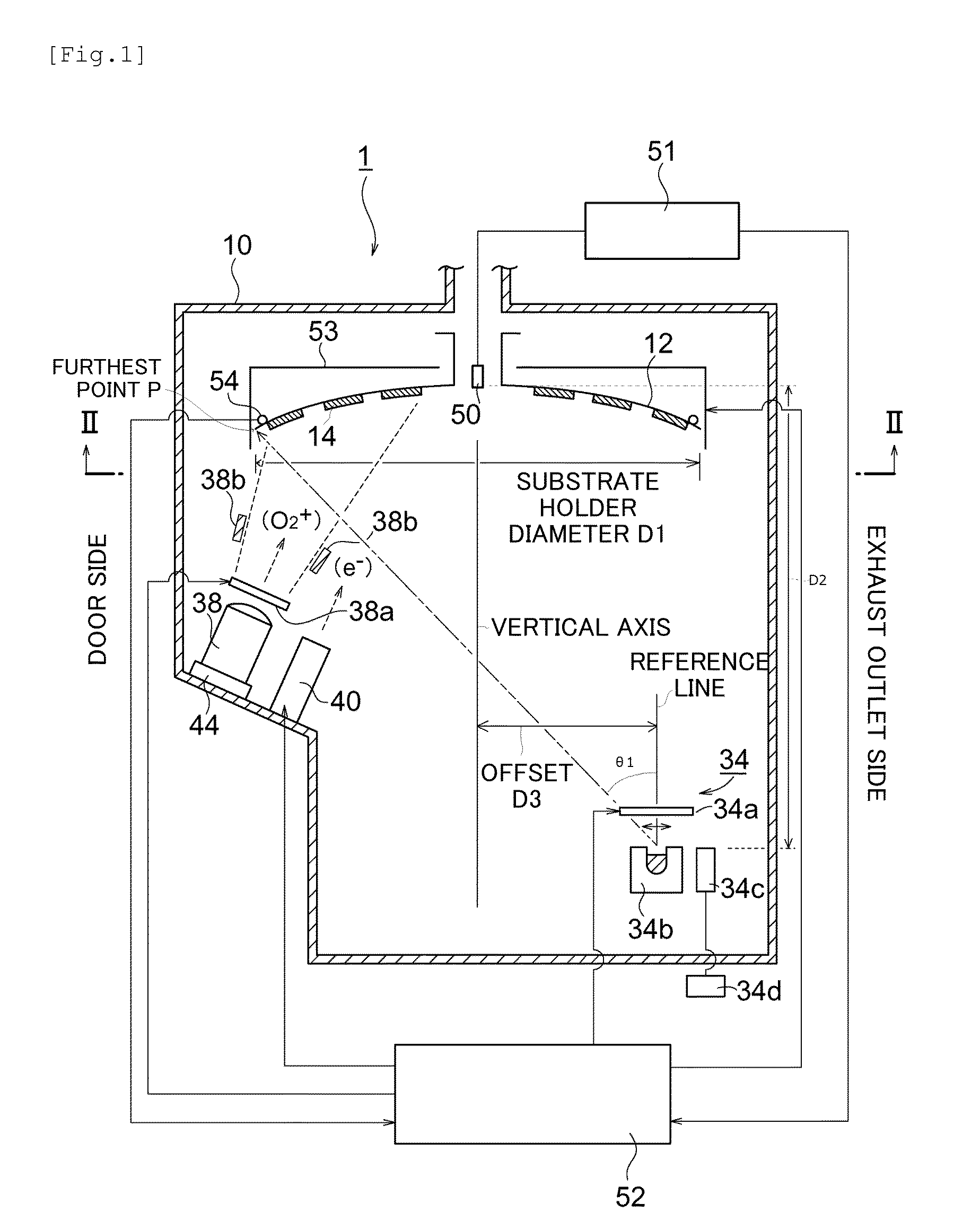
[0067]As shown in FIG. 1, a film formation apparatus 1 of the present embodiment comprises a vertical cylinder-shaped vacuum container 10.

[0068]The vacuum container 10 is a stainless-steel container having approximately a cylindrical shape like those normally used in well-known film formation apparatuses and has a ground potential. The vacuum container 10 is provided with an exhaust outlet (not shown but is on the right side when facing FIG. 1 in the present embodiment) and a vacuum pump (not shown) is connected via the exhaust outlet. By operating the vacuum pump, inside of the vacuum container 10 is exhausted to be a predetermined pressure (for example, 10−4 to 3×10⁻² Pa or so). A gas introduction tube (not shown) for introducing a gas to the inside is formed on the vacuum container 10. The vacuum container 10 may be connected to a load-lock chamber (not shown) via a door (not shown but is on the left side when facing FIG. 1 in the present embodiment).

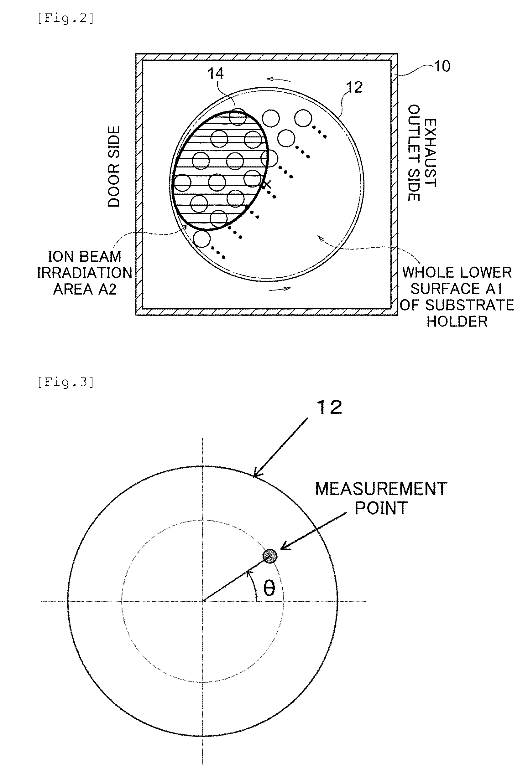
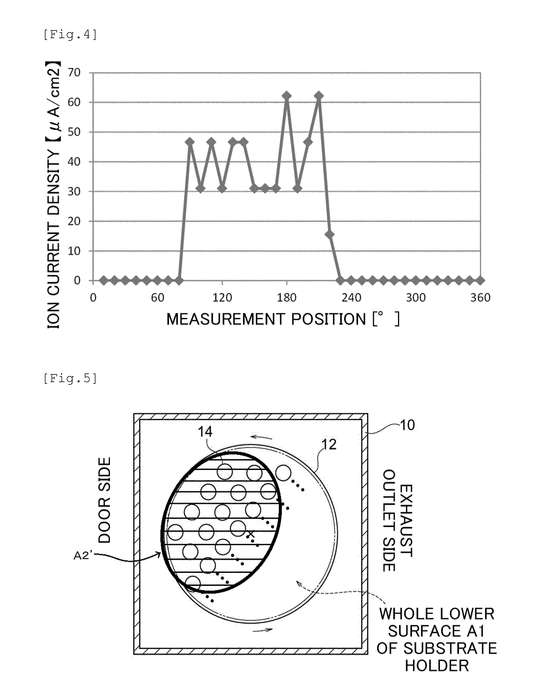
[0069]A substrate holder 12 i...

second embodiment

[0117]Next, an example of a film formation method (optical thin film formation method) using the film formation apparatus 1 will be explained.

[0118]In the present embodiment, the case of forming an optical filter thin film as an example of an optical thin film will be explained. An optical filter thin film formed in the present embodiment is formed by stacking a high refractive index substance and a low refractive index substance alternatively. However, the present invention can be applied also to formation of an optical filter composed of one or more kinds of vaporized substances (film formation material) and, in that case, the number and arrangement of evaporation source 34 may be changed arbitrarily.

[0119]Note that as a specific example of an optical filter to be produced in the present embodiment, a short wave pass filter (SWPF) and infrared cut filter are mentioned, however, other than those, it can be applied to a long wave pass filter, bandpass filter, ND filter and other thi...

third embodiment

[0158]Next, another embodiment of a film formation method (film formation method of functional thin film) using the film formation apparatus 1 will be explained.

[0159]In the present embodiment, as an example of a functional thin film, the case of forming an anti-fouling film configured by an organic substance will be explained. Note that an anti-fouling film is a film having water repellency and oil repellency and has a function of preventing adhesion of greasy dirt. Here, “prevent adhesion of greasy dirt” means in addition to not allowing greasy dirt to adhere thereto but it can be easily wiped off even if it gets. Namely, an anti-fouling film maintains oil repellency.

[0160]In the present embodiment, a mode of a film formation material for forming an anti-fouling film to be filled in the boat of the evaporation source 34 is not particularly limited and, for example, (a) those obtained by impregnating a hydrophobic reactive organic compound in porous ceramic or (b) those obtained by...


PUM

PropertyMeasurementUnit
accelerating voltageaaaaaaaaaa
irradiation currentaaaaaaaaaa
currentaaaaaaaaaa

Abstract

Provided is a film formation apparatus with which an anti-fouling film having high usability and antiwear performance may be formed efficiently. According to a film formation apparatus (1) of the present invention, a substrate holder (12) which comprises a basal body holding surface for folding a plurality of substrates (14) is disposed in a vacuum container (10) in a rotatable manner. The film formation apparatus (1) comprises an evaporation source (34) which is disposed in the vacuum container (10) in such a manner that a larger amount of film formation material may be supplied to a first area (A3) that is part of the basal body holding surface than to an area other than the first area (remaining area) when operated toward the substrate holder (12) in a rotation stop state; and an ion source (38) which is disposed in the vacuum container (10) in such a manner, arrangement, and/or direction that energetic particle irradiation may be made toward only a second area (A2) that is part of the basal body holding surface when operated toward the substrate holder (12) in the rotation stop state.

Description

TECHNICAL FIELD[0001]The present invention relates to a film formation method and a film formation apparatus suitable for a variety of film formation of optical thin films and functional thin films, etc. in particular.BACKGROUND ART[0002]In the field of optical thin films (including anti-reflection films) used for optical materials, such as an optical lens and optical filter, a slight decline in the optical characteristics thereof leads to a serious decline in characteristics as a final product. Therefore, an improvement of optical characteristics (for example, light transmissivity, etc.) has been demanded on optical thin films.[0003]There is known a technique of forming an anti-fouling film as an example of a functional thin film by going through the steps below (patent document 1). The method is to hold a plurality of substrates as processing objects allover a substrate holding surface of a substrate holder, then, to rotate the substrate holder in a vacuum chamber. Next, while mai...

Claims


Application Information

Patent Timeline
Patent Type & Authority Applications(United States)
IPC IPC(8): C23C14/58
CPCC23C14/58C23C14/24C23C14/0031C23C14/022C23C14/541C23C14/546
Inventor SHIONO, ICHIROHAYASHI, TATSUYAJIANG, YOUSONGNAGAE, EKISHUMIYAUCHI, MITSUHIROSAMORI, SHINGO
Owner SHINCRON KK
Why Eureka
Try Eureka