
Negative electrode active material for energy storage devices and method for making the same

a technology of active materials and negative electrodes, which is applied in the direction of non-metal conductors, cell components, conductors, etc., can solve the problems of graphite negative electrodes, serious safety issues, and burning of batteries

Inactive Publication Date: 2014-09-04
IMRA AMERICA
View PDF4 Cites 31 Cited by
  • Summary
  • Abstract
  • Description
  • Claims
  • Application Information

AI Technical Summary

Benefits of technology

The patent describes a new type of material that can be used as a negative electrode active material in energy storage devices. This material is made by combining a titanium compound and a niobium compound in a solution, adding water to create solid particles, and then heating them to create Nb-doped TiO2(B) particles. These particles have been found to be effective in energy storage devices, particularly batteries. The technical effect of this patent is the creation of a new and effective material for energy storage devices that can improve their performance and efficiency.

Problems solved by technology

The deposition of the lithium may cause serious safety issues including burning of the battery.
In addition to the potential voltage over-shooting issue, a graphite negative electrode may also have issues resulted from a solid electrolyte interface (SEI) layer, which is generated from decomposition of an organic electrolyte and a lithium salt at a voltage +).
TiO2(B) is then obtained after heating the hydrogen titanate at a temperature ranging from 400° C. to 600° C. This technique is tedious because of the ion-exchange process, which may take several days.
The increase of the heating temperature, however, may change the crystal structure of the obtained sample, which is not desirable.
The instability of TiO2(B) obtained from the solvothermal process at a relatively high temperature (e.g., 450° C. and above) may limit its applications.
For example, it will be difficult to apply a carbon coating onto these TiO2(B) particles by using a wet chemistry process since a heating temperature as high as 450° C. and above generally is needed to decompose organics into carbon.

Method used

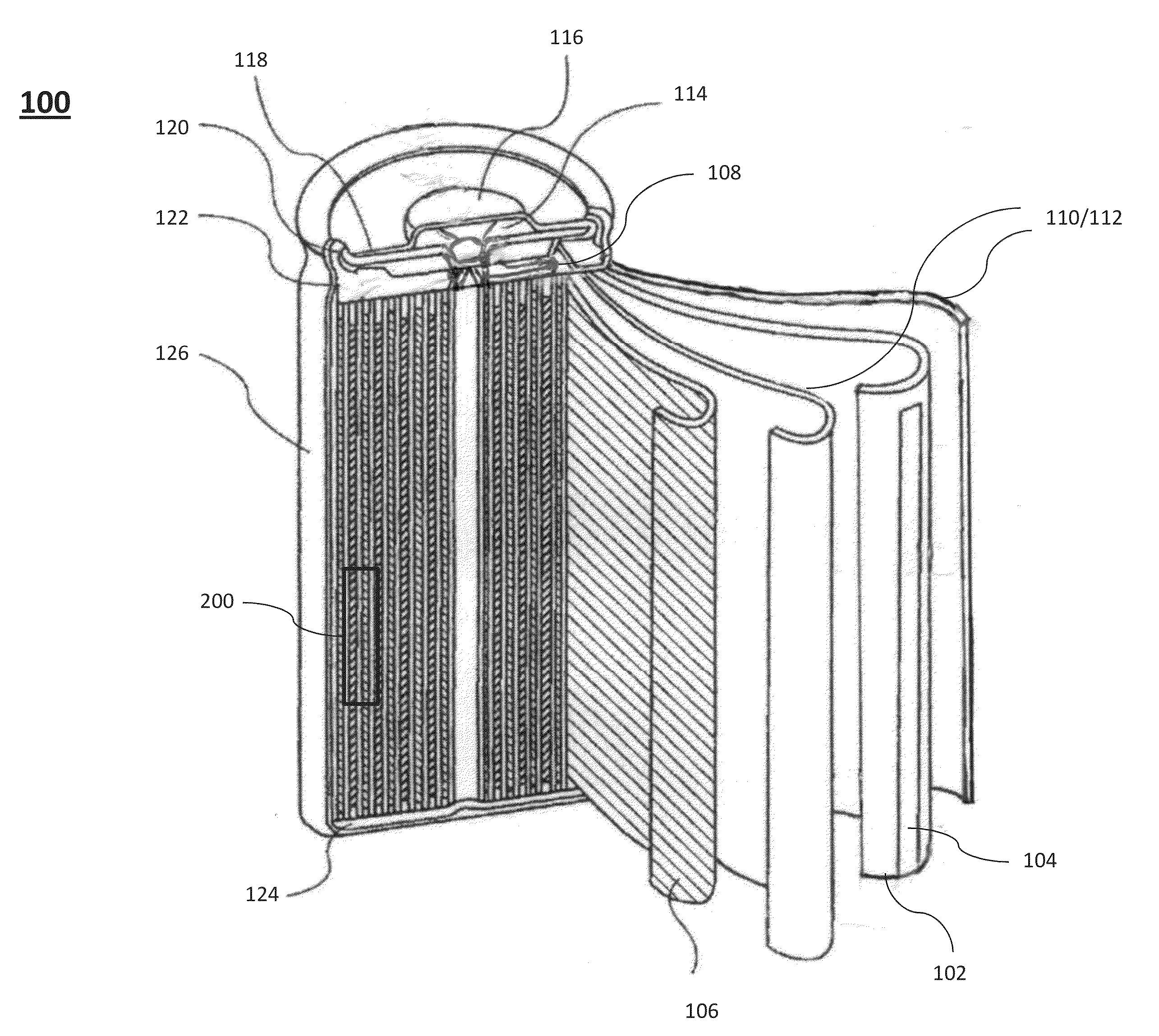
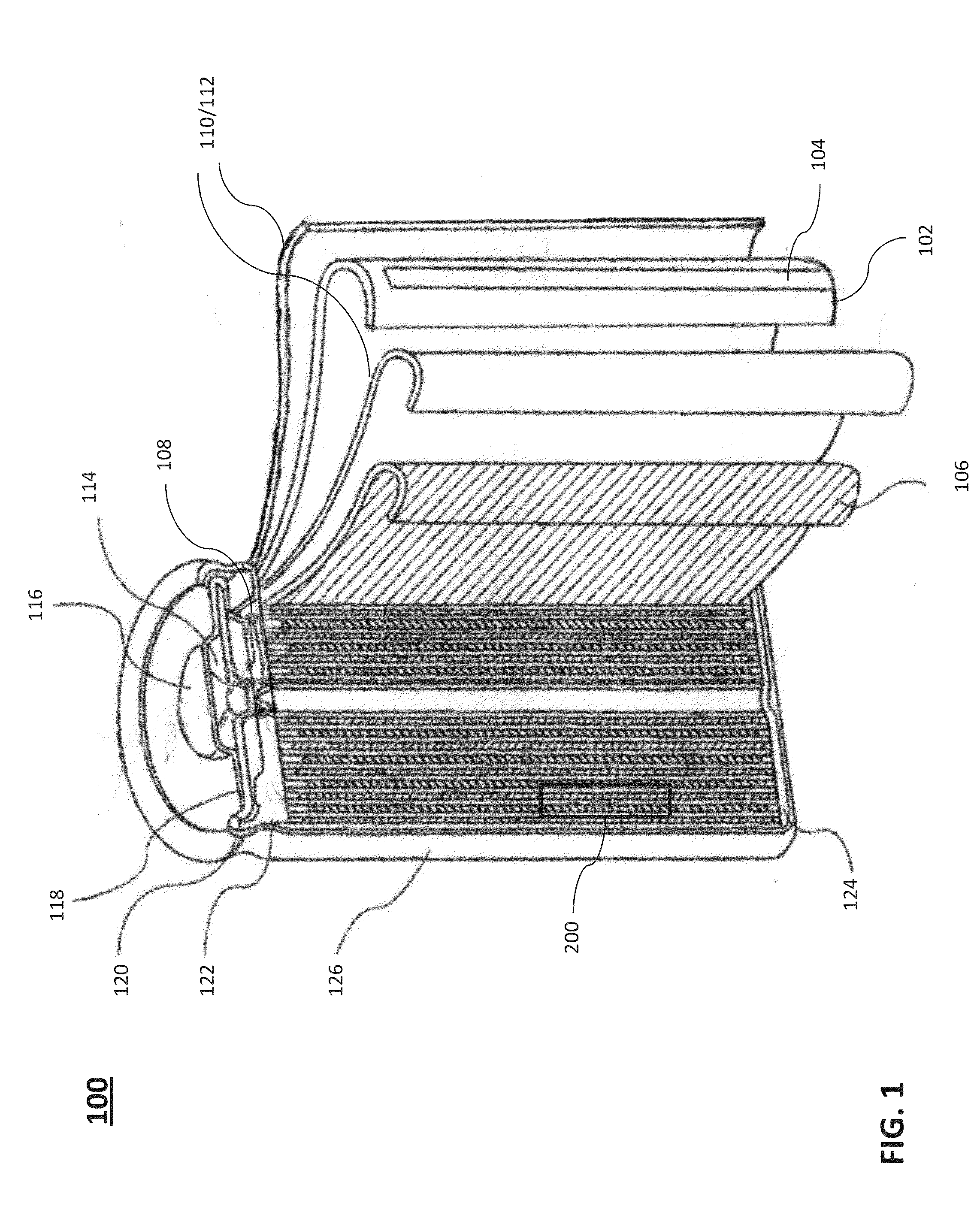
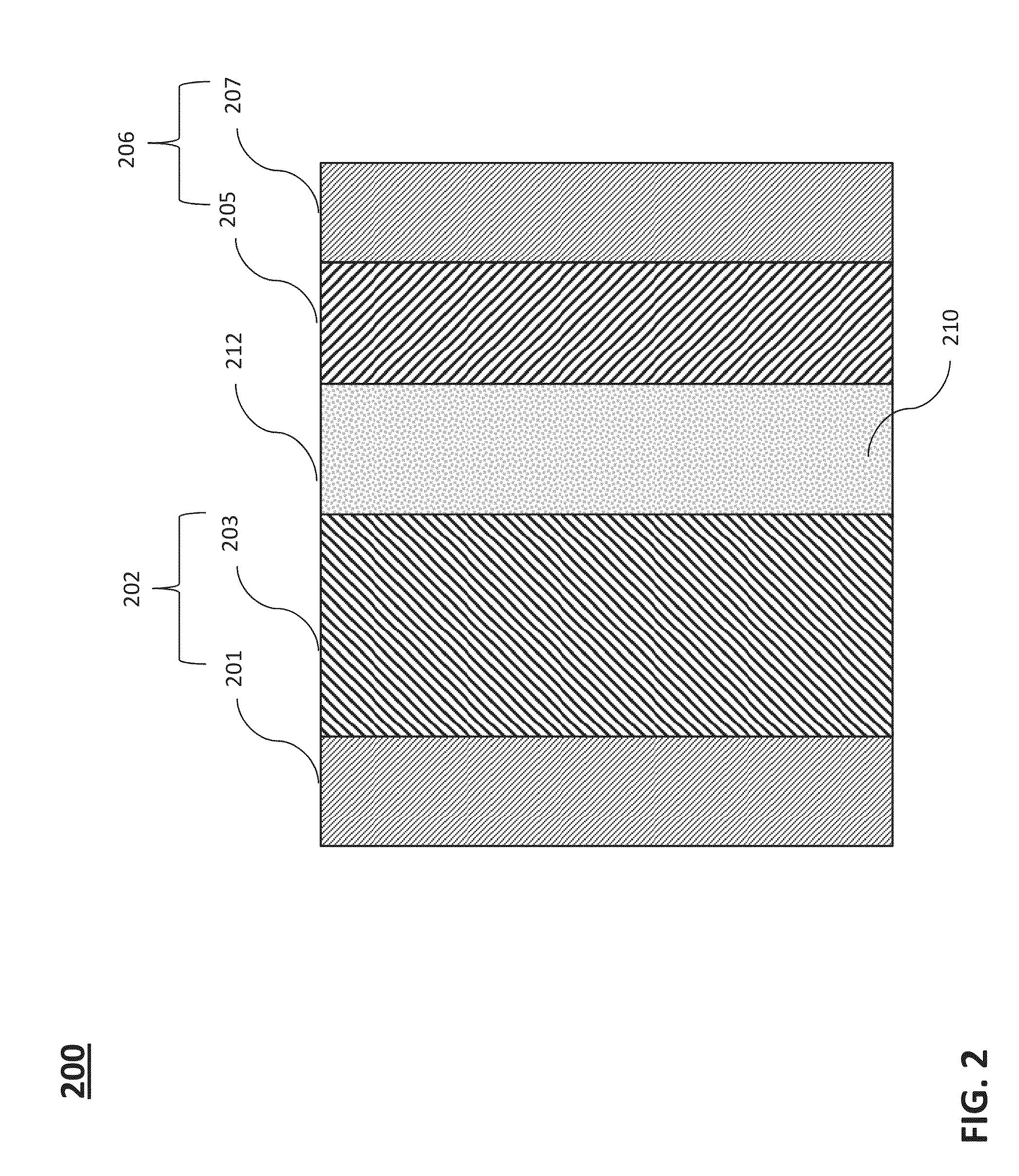

Image

  • Negative electrode active material for energy storage devices and method for making the same
  • Negative electrode active material for energy storage devices and method for making the same
  • Negative electrode active material for energy storage devices and method for making the same

Examples


example 1

TiO2 / Carbon Black Treated at Various Temperatures

[0075]TiO2 / carbon black was prepared according to Liu et al., “Nanosheet-Constructed Porous TiO2—B for Advanced Lithium Ion Batteries”, Advanced Materials, vol. 24, (May 18, 2012), pp. 3201-3204, which is incorporated herein by reference in its entirety. More specifically, 1 ml TiCl4 was dissolved in 80 ml ethylene glycol. Acetylene black was then dispersed in the solution as needed, followed by adding 1.8 g aqueous ammonia (28 wt %) under stirring. The obtained solution was refluxed at about 185° C. to 190° C. in open air for 4 hours. Generated particles were collected by vacuum filtration with a regular filter paper (particle retention: 8 to 12 μm). The generated particles were dried at 110° C. overnight and then heated at either 350° C. or 450° C. in air for 2 hours. The obtained samples are named as TiO2-1-110C, TiO2-1-350C, and TiO2-1-450C.

[0076]XRD patterns for the TiO2 samples heated at 110° C., 350° C. and 450° C. are shown in...

example 2

TiO2-2-450C and Nb0.1Ti0.9O2-2-450C

[0080]TiO2-2-450C and Nb0.1Ti0.9O2-2-450C were prepared by the solvothermal process. In one exemplary process for synthesizing TiO2, about 2.6 ml TiCl4 was dissolved in 30 ml ethylene glycol. 5.4 g aqueous ammonia (28 wt %) was then added into the above solution under stirring. The obtained solution was refluxed (e.g., at about 185° C.) in open air for 4 hours. Particles were collected by vacuum filtration with a regular filter paper (particle retention: 8 to 12 μm). The generated particles were dried at 110° C. overnight and then heated at 450° C. in air for 2 hours. The preparation procedure for Nb0.1Ti0.9O2 was the same as TiO2 except that 0.72 g NbCl5 was added in ethylene glycol as the source for Nb, besides adding TiCl4. The 450° C.-heated samples are named as TiO2-2-450C and Nb0.1Ti0.9O2-2-450C.

[0081]XRD patterns for TiO2-2-450C and Nb0.1Ti0.9O2-2-450C are shown in FIG. 5. The XRD pattern for TiO2-2-450C might be a good fit for an anatase-on...

example 3

Nb-Doped TiO2 with Various Nb / Ti Molar Ratios

[0085]Five samples were made with various molar ratios of Nb / Ti (e.g., about 100 / 0, 50 / 50, 25 / 75, 10 / 90, and 5 / 95) through the solvothermal process. The amounts of reactants are listed in Table 3. As-synthesized samples before the heating post-treatment step are identified as Nb1Ti0, Nb1Ti1, Nb1Ti3, Nb1Ti9, and Nb1Ti19, respectively.

TABLE 3SampleNb1Ti19Nb1Ti9Nb1Ti3Nb1Ti1Nb1Ti0NbCl5 (g)0.120.240.581.101.97TiCl4 (ml)0.940.880.710.450Acetylene black0.110.110.110.110.11Ethylene glycol (ml)8080808080Aqueous ammonia1.81.81.81.81.8(about 28 wt %)

[0086]Samples Nb1Ti0-450C, Nb1Ti1-450C, Nb1Ti3-450C, Nb1Ti9-450C, and Nb1Ti19-450C were obtained by heating Nb1Ti0, Nb1Ti1, Nb1Ti3, Nb1Ti9, and Nb1Ti19 at 450° C. in air for 2 hours, respectively. Samples Nb1Ti0-450C, Nb1Ti1-450C, Nb1Ti3-450C, and Nb1Ti9-450C were then heated at 550° C. for 2 hours in air to form Nb1Ti0-550C, Nb1Ti1-550C, Nb1Ti3-550C, and Nb1Ti9-550C, respectively. Samples Nb1Ti1-550C, N...


PUM

PropertyMeasurementUnit
particle sizesaaaaaaaaaa
particle sizeaaaaaaaaaa
temperatureaaaaaaaaaa

Abstract

The described embodiments provide an energy storage device that includes a positive electrode including a material that stores and releases ion, a negative electrode including Nb-doped TiO2(B), and a non-aqueous electrolyte containing lithium ions. The described embodiments provide a method including the steps of combining at least one titanium compound and at least one niobium compound in ethylene glycol to form a precursor solution, adding water into the precursor solution to induce hydrolysis and condensation reactions, thereby forming a reaction solution, heating the reaction solution to form crystallized particles, collecting the particles, drying the collected particles, and applying a thermal treatment at a temperature >350° C. to the dried particles to obtain Nb-doped TiO2(B) particles.

Description

BACKGROUND[0001]1. Field of the Invention[0002]The present invention relates to lithium-based energy storage devices generally, and, in particular, to negative electrode active materials for lithium-based energy storage devices.[0003]2. Description of the Related Art[0004]In conventional lithium ion batteries, negative electrode active materials are based on graphite, which generally has lithium intercalation potential at about 0.1V (relative to a reference Li / Li+ redox potential). Lithium may be deposited onto an electrode from an electrolyte at a high charge rate because of over-shooting of the potential, which is expected because of an increased internal voltage drop with an increased charge rate. The deposition of the lithium may cause serious safety issues including burning of the battery. In addition to the potential voltage over-shooting issue, a graphite negative electrode may also have issues resulted from a solid electrolyte interface (SEI) layer, which is generated from d...

Claims


Application Information

Patent Timeline
Patent Type & Authority Applications(United States)
IPC IPC(8): H01M4/485H01M4/36H01G11/06C01G23/053H01M4/04H01M4/1391H01M10/0525H01M4/62
CPCH01M4/485H01M10/0525H01M4/366H01M4/625H01G11/06H01M4/0471H01M4/1391C01G23/0536C01G23/053B82Y30/00C01P2002/30C01P2002/32C01P2002/50C01P2002/52C01P2002/54C01P2002/72C01P2004/61C01P2004/62C01P2004/64C01P2004/80C01P2006/40H01G11/32H01G11/46H01G11/86Y02E60/10Y02E60/13
Inventor TAN, BINGHU, ZHENDONGHE, GUANGHUICHE, YONG
Owner IMRA AMERICA
Learn More