Test strip detection system

a detection system and strip technology, applied in the field of biomedical appliances, can solve the problems of low testing efficiency, difficult to realize simultaneous test of multiple indexes of samples, and rare use of rfid in biomedical sample test, etc., to achieve fast and accurate quantification of sample indexes of a plurality of components, good spectral features and photochemical stability

Active Publication Date: 2014-09-18
CHENGDU LINGYU BIOTECH
View PDF1 Cites 24 Cited by
  • Summary
  • Abstract
  • Description
  • Claims
  • Application Information

AI Technical Summary

Benefits of technology

[0046]In comparison with the prior art, the invention has the following beneficial effects:
[0047]1) The sample test is fast, and the quantitative testing result of a sample can be obtained rapidly and accurately in a few minutes; when the test strip for sample test is a quantum dot-marked test strip, the system of the invention can rapidly and accurately quantify index of a plurality of components in the sample simultaneously in a few minutes via a single operation. Quantum dot (QD), which was developed in 1990s, is a semiconductor nano crystal with good spectral features and photochemical stability, and has characteristics of a high fluorescence radiation efficiency, a wide range of excited spectrum, a narrow range of emission spectrum, a long fluorescence lifetime, a large Stokes displacement, a grain size approaching to a biologic molecule, and multifunctionalization after surface modification. As a new-generation biologic fluorescence marker, quantum dot has a profound and lasting potential to replace the traditional organic dyestuff. Quantum dots with different grain sizes, types and structures can generate a continuous luminescence spectrum peak at different characteristic wavelengths, further, the luminescence spectrum peaks at characteristic wavelengths generated by the quantum dot mixture do not overlap with one another. Therefore, if the corresponding reaction molecules of the detected substance are marked with different quantum dots respectively, and a mixture thereof is coated on a immunochromatographic test strip to react with a sample to be detected, the concentrations of a plurality of components of the sample can be detected rapidly and accurately in a few minutes by determining the specific fluorescence signal of the test strip.
[0048]2) The amount of the sample required for the sample testing is reduced, and several microliters to several dozens of microliters of the sample is sufficient for the testing.
[0049]3) The test strip testing system according to the invention may be embodied as a large-sized detection instrument for use by large, middle and small organizations, in this case, the data processor 6 of the test strip testing system may be embodied as a PC; or, the test strip testing system may be embodied as a small-sized portable detector for on-site instant detection in a family, a supermarket, a street, an invalid bed and in people's daily life, in this case, the data processor 6 may be embodied as a microprocessor.
[0050]4) The operation of the test strip testing system is simple and the quality control is convenient, so that an ordinary person can realize the rapid quantitative detection of multiple indexes of a sample without the aid of an additional equipment or reagent, thereby overcoming the limitation of the prior art where the sample test, especially quantitative detection of multiple components, must be operated by a professional technician. The function of the voice module 34 of the invention to output the testing result information vocally is helpful for operators with poor eyesight (for example, an elderly person) to listen to the testing result. To conduct the sample test in the invention, a detector only needs to insert on site a test strip 15 applied with a sample into a test strip card 1 on which an electronic tag corresponding to test strips of the same batch as the test strip 15 is installed, then insert the test strip card 1 inserted with the test strip into the test strip card receptacle 33 of the testing device 2 of the system, and then dip the sample absorption end of the extended test strip into the sample to be tested, after that, the testing result may be accurately obtained in a few minutes; moreover, by pressing a transmission key, the testing result information may be further sent on site to a remote server for data management and information consultation feedback. The detection is rapid, convenient and simple, and the result is objective with a high sensitivity.
[0051]5) The test strip 15 in the test strip card 1 is disposable; the card box 16 of the test strip card 1 for receiving the disposable test strip 15 and the electronic tag 20 installed on the card box 16 are matched with test strips of the same batch; and the test strip testing device 2 is a durable general-purpose product. To test a different sample, it only needs to place the corresponding test strip and the corresponding card box 16 of the test strip card 1 into the system, so that rapid quantitative detection of the sample may be realized. A testing device 2 may be donated to a loyal user, to attract the user to buy the disposable test strips 15 matching with the testing device 2 and the test strip card box 16 on which an electronic tag 20 matching with test strips of the same batch is installed. The test strip15 and the card box 16 of the test strip card on which an electronic tag 20 is installed are inexpensive, and thus can be afforded by common consumers.

Problems solved by technology

However, it has the following disadvantages: 1) a sample can only be rapidly detected qualitatively via a colloidal gold test strip, and no quantitative detection of a sample can be realized, thus it is generally used only for the primary screening testing of a sample, and no validation report of the testing result can be provided, therefore, the clinical application range thereof and the detection effect evaluation thereof are limited; and 2) generally, only one sample index can be tested by one test strip, so it is difficult to realize simultaneous test of multiple indexes of a sample, resulting in a low testing efficiency.
However, the RFID is seldom used for a biomedical sample test.
However, it has the following disadvantages: 1) the test system with an RFID read and write function, which is described in this design, is only directed to a colloidal gold test strip, and the system is consisted of a radio-frequency card reading module, a radio frequency label and a mastercontrol monolithic processor, but the solving of the important problem as to how the system specifically realizes the quantitative detection of a sample via a colloidal gold test strip is not involved; 2) it is difficult for a colloidal gold test strip to realize the simultaneous detection of multiple indexes of a sample; and 3) the test strip card of this design has a complex structure and its manufacturing is difficult and expensive, and the detection fee bearing capability of a subject subjected to the sample testing is not considered.
At present, the test strip is fixed in the card box of the test strip card and cannot be replaced flexibly as desired depending on different samples, and the subject that is subjected to the sample testing has to bear an unnecessary cost for the test strip card box carrying the test strip, so that the economic burden of the subject is increased.
However, it has the following disadvantages: 1) the information stored on the radio frequency identification card is not a standard curve of a substance be detected, and for the quantitative detection of a sample, it will be simpler, more convenient and more accurate when a standard curve of the substance to be detected is stored; and 2) in these two patents / patent applications, the detection fee bearing capability of a subject that is subjected to the sample testing is still not considered synthetically from the structure of the test paper strip.
By the structure of the test paper strip, the built-in test paper still cannot be replaced flexibly as desired depending on different samples.
ZL200920066534.9 all have such a problem, and remote data management on the testing result of a sample and rapid and accurate polycomponent quantification of a sample cannot be realized in the above patents.

Method used


Image

  • Test strip detection system
  • Test strip detection system
  • Test strip detection system

Examples


embodiment 1

Structure, Work Flow and Testing Method of a Test Strip Testing System without Remote Data Management and Remote Information Feedback Capabilities According to the Invention (as Illustrated in Combination with FIGS. 1, 2, 5, 6, 7 and 8)

[0074]1. The Structure of the Test Strip Testing System

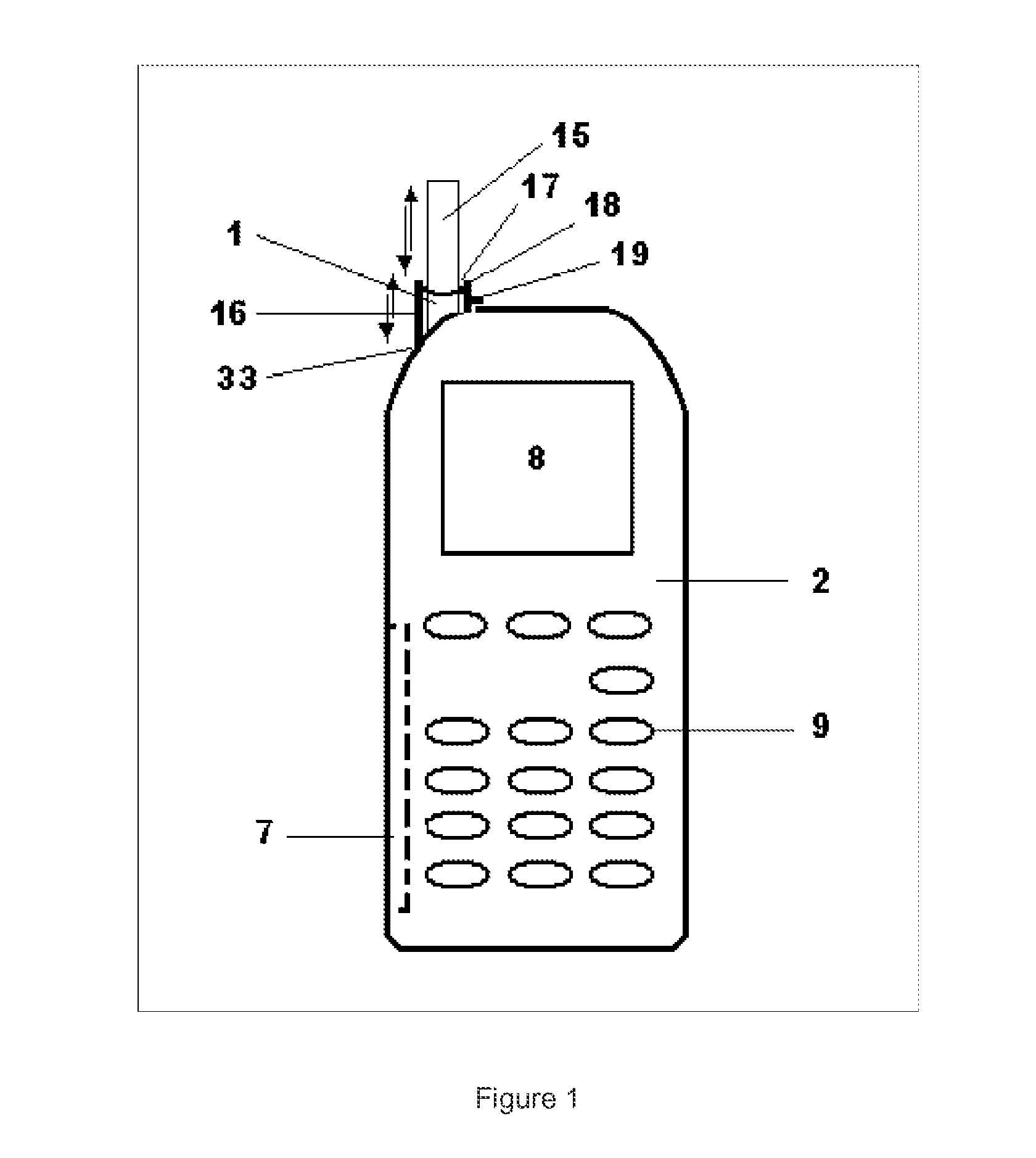
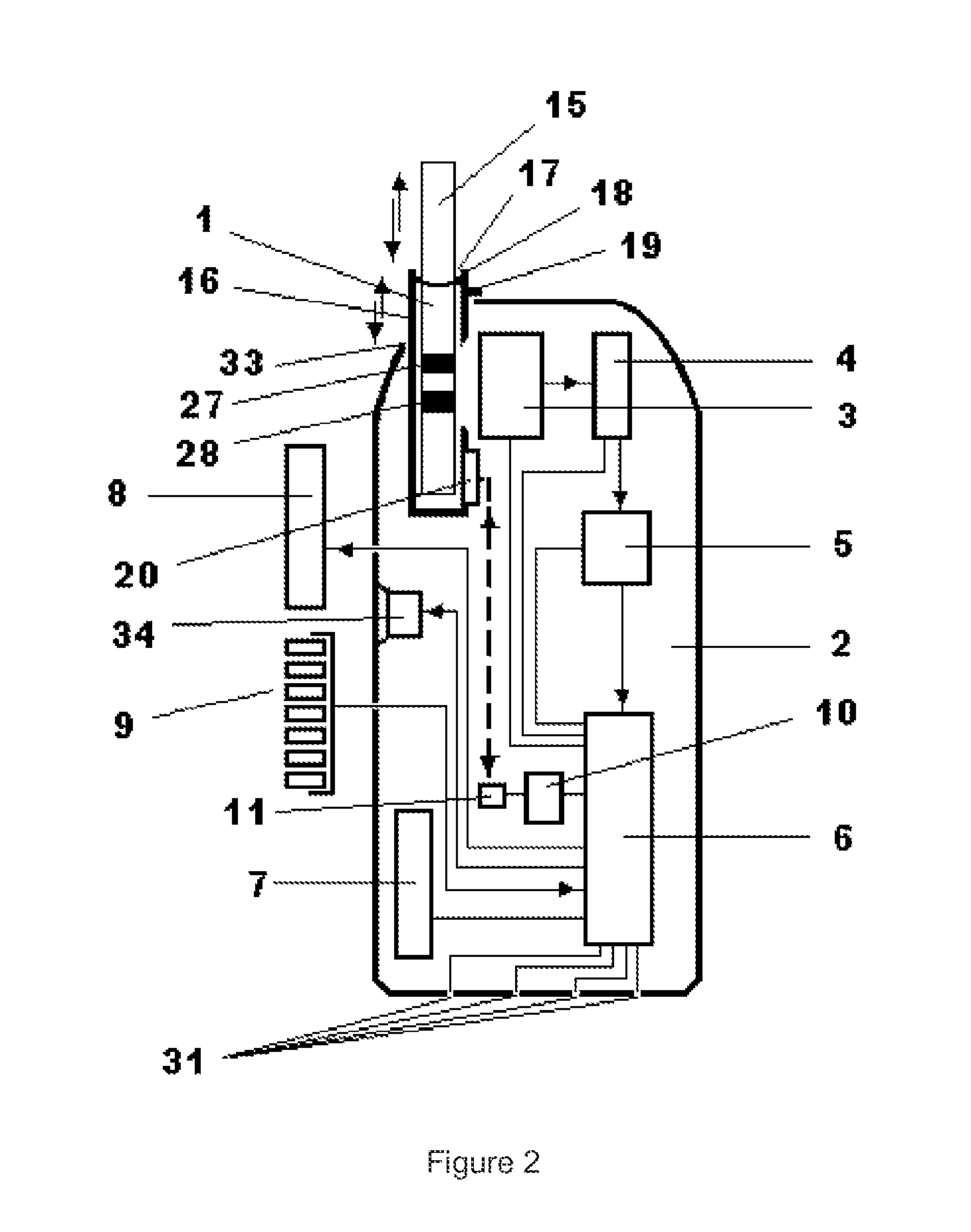
[0075]FIGS. 1 and 2 are block diagrams respectively showing the external and internal structures of a test strip testing system including a testing device of a mobile phone form according to an embodiment of the invention, where the test strip testing system is without remote data management and remote information feedback capabilities.

[0076]Referring to both FIGS. 1 and 2, the test strip testing system includes a test strip card 1 and a testing device 2. The test strip card 1 includes a card box 16, an optional test strip 15 inserted in the card box 16, and an electronic tag 20 that is installed on the card box 16 and configured to store test strip information. The testing device 2 includes an op...

embodiment 2

Structure, Work Flow and Testing Method of a Test Strip Testing System with Remote Data Management and Remote Information Consultation Feedback Capabilities According to the Invention (as Illustrated in Combination with FIGS. 3, 4, 5, 6, 7 and 8)

[0108]1. The Structure of the Test Strip Testing System

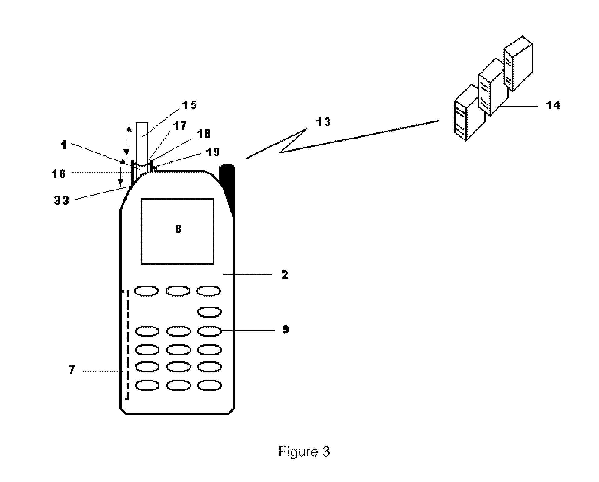
[0109]FIGS. 3 and 4 are block diagrams respectively showing the external and internal structures of a test strip testing system including a testing device of a mobile phone form according to an embodiment of the invention, where the test strip testing system has remote data management and remote information consultation feedback capabilities.

[0110]Referring to both FIGS. 3 and 4, the test strip testing system includes a test strip card 1, a testing device 2 and a wireless network system 13 that includes a remote server 14. The test strip card 1 includes a card box 16, an optional test strip 15 inserted in the card box 16, and an electronic tag 20 that is installed on the card box 16 and ...

embodiment 3

Detection of Blood Serum Tumour Markers AFP, CEA and PSA Via the Test Strip Testing System Inserted with a Quantum Dot-Marked Test Strip (Single Detection for a Plurality of Components)

[0144]1. Manufacturing of a Quantum Dot-Marked Test Strip

[0145]The quantum dot-marked test strip 15 includes a sample pad 21, a glass fiber membrane binding pad 22, an analysis membrane 23 with a test line 27 and a control line 28, a super-absorbent pad 24 and a test strip reaction end position indication label 25, which are arranged sequentially and stuck mutually. The glass fiber membrane binding pad 22 is coated with a mixture of quantum dot-marked alphafetoprotein (AFP) monoclonal antibody, quantum dot-marked carcinoembryonic antigen (CEA) monoclonal antibody and quantum dot-marked prostate-specific antigen (PSA) monoclonal antibody; the test line 27 is coated with a mixture of AFP antibody, CEA antibody and PSA antibody; and the control line 28 is coated with a secondary antibody quality control ...


PUM

PropertyMeasurementUnit
included angleaaaaaaaaaa
sizeaaaaaaaaaa
sizeaaaaaaaaaa

Abstract

A test strip detection system, comprising a test strip card (1) and a detection device (2); the test strip card (1) comprises a card box (16), a built-in test strip (15) and an electronic label (20) matched with the built-in test strip (15); the electronic label (20) stores parameters such as the standard working curve of an object to be detected and the like; the detection device (2) comprises an optical system (3), a photoelectric detector (4), an analog / digital converter (5), a data processing device (6), an electronic label read-write module (10) with an aerial (11), a voice module (34), a cell box (7) and an output display device (8). The system further comprises a wireless communication module (12) and a wireless network system (13) connected with the wireless communication module (12) and comprising a remote server (14). The data processing device (6) calculates a sample detection result according to the characteristic frequency optical signals transmitted by a test strip detection band (27) and a quality control band (28) in combination with an electronic label (20) transmission parameter; the detection result is displayed on the output display device (8); the voice module (34) vocally prompts the detection result at the same time; the detection result is transmitted to the remote server (14) via the wireless communication module (12) for data management and information feedback.

Description

FIELD OF THE INVENTION[0001]The present invention relates to the field of biomedical appliances, and in particular, to a test strip testing system. The test strip testing system is operable to automatically scan and detect a test strip on which a substance to be detected is applied and interpret a testing result, thereby realizing the quantitative detection of various detected substance such as pathogen, antigen, antibody, banned drug, dread disease (tumour, cancer, cardiovascular disease, diabetes, etc.), pesticide residue, food security biological detection, etc., and sending the testing result and the related information to a remote server for management and information consultation feedback.BACKGROUND OF THE INVENTION[0002]At present, biomedical diagnosis and detection products generally develop rapidly toward two directions, i.e., a development direction toward highly integrated and automatized large-scale products and a development direction toward simple, rapid and easily pop...

Claims


Application Information

Patent Timeline
Patent Type & Authority Applications(United States)
IPC IPC(8): G01N33/569
CPCG01N33/56983G01J3/0208G01J3/0218G01J3/0264G01J3/0272G01J3/0283G01J3/0291G01J3/42G01N21/8483
Inventor MA, YICAIGU, MINMA, LING
Owner CHENGDU LINGYU BIOTECH
Why Eureka
Try Eureka