Ion source and ion beam device using same

a technology of ion beam and ion source, which is applied in the direction of discharge tube main electrodes, instruments, nuclear engineering, etc., can solve the problems of diffraction effect and aberration, and achieve the effect of removing shaking or the like in the sample observation image and ultra-high resolution

Inactive Publication Date: 2014-10-09
HITACHI HIGH-TECH CORP
View PDF13 Cites 25 Cited by
  • Summary
  • Abstract
  • Description
  • Claims
  • Application Information

AI Technical Summary

Benefits of technology

[0039]According to the present invention, in a charged particle beam microscope, it is possible to allow a mechanical vibration amplitude of a distal end of an emitter tip to be small, to obtain an ultra-high resolution sample observation image, and to remove shaking or the like in a sample observation image.

Problems solved by technology

In addition, with respect to the electron beam, since the properties of electrons as a wave cannot be neglected, aberration occurs due to the diffraction effect.

Method used


Image

  • Ion source and ion beam device using same
  • Ion source and ion beam device using same
  • Ion source and ion beam device using same

Examples


first embodiment

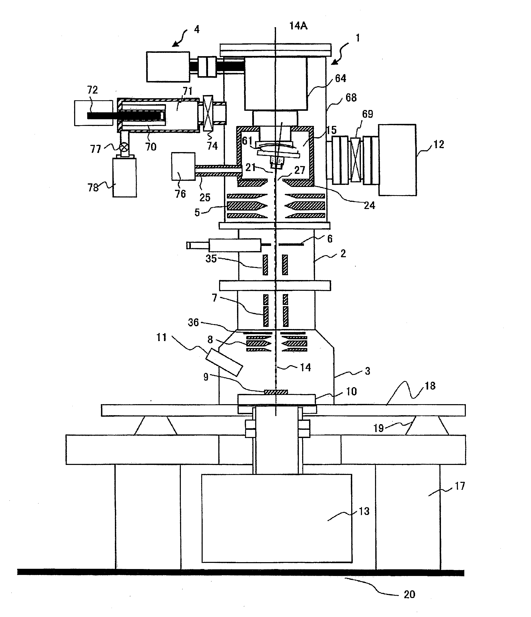
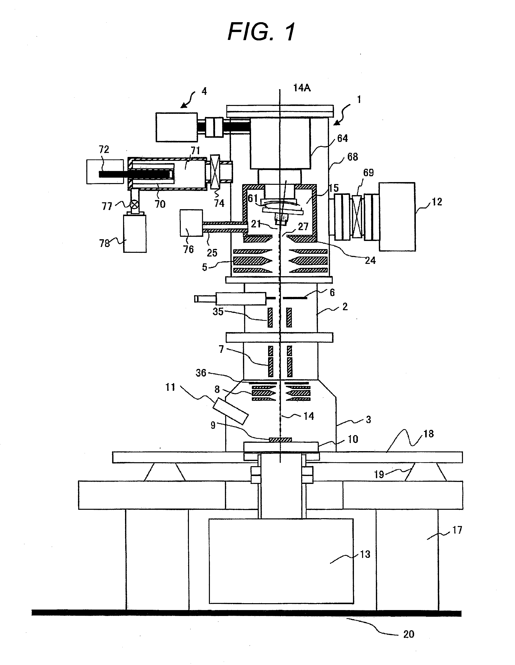
[0051]An example of a charged particle microscope according to the present invention will be described with reference to FIG. 1. Hereinafter, a first embodiment of a scanning ion microscope apparatus as an ion beam apparatus will be described. The scanning ion microscope according to the embodiment is configured to include a gas field ion source 1, an ion beam irradiation system column 2, a sample chamber 3, and a cooling mechanism 4. Herein, the gas field ion source 1, the ion beam irradiation system column 2, and the sample chamber 3 are a vacuum chamber.

[0052]Although the configuration of the gas field ion source 1 will be described later in detail, a needle-shaped emitter tip 21 and an extraction electrode 24 provided to face the emitter tip and to include an opening 27 through which ions pass are included within a vacuum chamber 68. An ionization chamber 15 is provided to increase a pressure of ionized gases in the vicinity of the emitter tip. A gas supply pipe 25 provided at t...

second embodiment

[0097]Next, an example of the charged particle beam apparatus according to the embodiment will be described with reference to FIG. 8. In FIG. 8, the cooling mechanism 4 of the charged particle beam apparatus illustrated in FIG. 1 will be described in detail. In the example, the cooling mechanism 4 employs a helium circulation type.

[0098]The cooling mechanism 4 according to the embodiment cools the helium gas as a coolant by using a GM type refrigerator 401 and heat exchangers 402, 405, 409, and 412 and circulates the cooled helium gas by the compressor unit 400. The helium gas compressed at, for example, 0.9 MPa by the compressor and having a room temperature of 300 K is allowed to flow into the heat exchanger 402 through the pipe 409 and exchanges heat with the low-temperature backward helium gas to be described later to be cooled down to a temperature of about 60 K. The cooled helium gas is transported through the pipe 403 in the insulated transfer tube 404 to flow into the heat e...

third embodiment

[0120]Next, a charged particle microscope capable of observing a sample surface, performing sample processing, and observing an internal portion of the sample to perform complex analysis of the sample by using a hybrid particle source which has a distal end of an emitter tip formed in a nano-pyramid configured with atoms and extracts an ion beam or electrons from the needle-shaped emitter tip will be described with reference to FIG. 11.

[0121]The same configurations as those of the first and second embodiments will be omitted in description.

[0122]The charged particle microscope according to the embodiment is configured to include a hybrid particle source 301 which has a distal end of an emitter tip formed in a nano-pyramid configured with atoms and extracts an ion beam or electrons from a needle-shaped emitter tip, a hybrid irradiation system 302 which irradiates a sample with the electron beam and the ion beam, a sample stage 303, a secondary particle detector 304 which detects seco...


PUM


Abstract

Provided is a charged particle beam microscope which has a small mechanical vibration amplitude of a distal end of an emitter tip, is capable of obtaining an ultra-high resolution sample observation image and removing shaking or the like of the sample observation image. A gas field ion source includes: an emitter tip configured to generate ions; an emitter-base mount configured to support the emitter tip; a mechanism configured to heat the emitter tip; an extraction electrode installed to face the emitter tip; and a mechanism configured to supply a gas to the vicinity of the emitter tip, wherein the emitter tip heating mechanism is a mechanism of heating the emitter tip by electrically conducting a filament connecting at least two terminals, the terminals are connected by a V-shaped filament, an angle of the V shape is an obtuse angle, and the emitter tip is connected to a substantial center of the filament.

Description

TECHNICAL FIELD[0001]The present invention relates to a charged particle microscope and an ion microscope, and more particularly, to a gas field ion source and an ion beam device.BACKGROUND ART[0002]The surface structure of a sample can be observed by scanning and irradiating the sample with an electron beam and detecting secondary charged particles emitted from the sample. This is called a “scanning electron microscope (hereinafter referred to as a SEM). On the other hand, the surface structure of a sample can also be observed by scanning and irradiating the sample with an ion beam and detecting secondary charged particles emitted from the sample. This is called a “scanning ion microscope” (hereinafter, referred to a SIM). Particularly, the irradiation of the sample with ion species with light mass such as hydrogen, helium, or the like makes a sputtering function become relatively small, so that the irradiation is suitable for sample observation.[0003]The ion beam has a characteris...

Claims


Application Information

Patent Timeline
Patent Type & Authority Applications(United States)
IPC IPC(8): H01J27/02H01J37/26
CPCH01J2237/0216H01J2237/0807H01J37/26H01J37/28H01J27/022H01J37/08
Inventor SHICHI, HIROYASUMATSUBARA, SHINICHIOSE, YOICHIKAWANAMI, YOSHIMIARAI, NORIAKI
Owner HITACHI HIGH-TECH CORP
Why Eureka
Try Eureka