

Redox flow secondary battery and electrolyte membrane for redox flow secondary battery
- Summary
- Abstract
- Description
- Claims
- Application Information
AI Technical Summary
Benefits of technology
Problems solved by technology
Method used
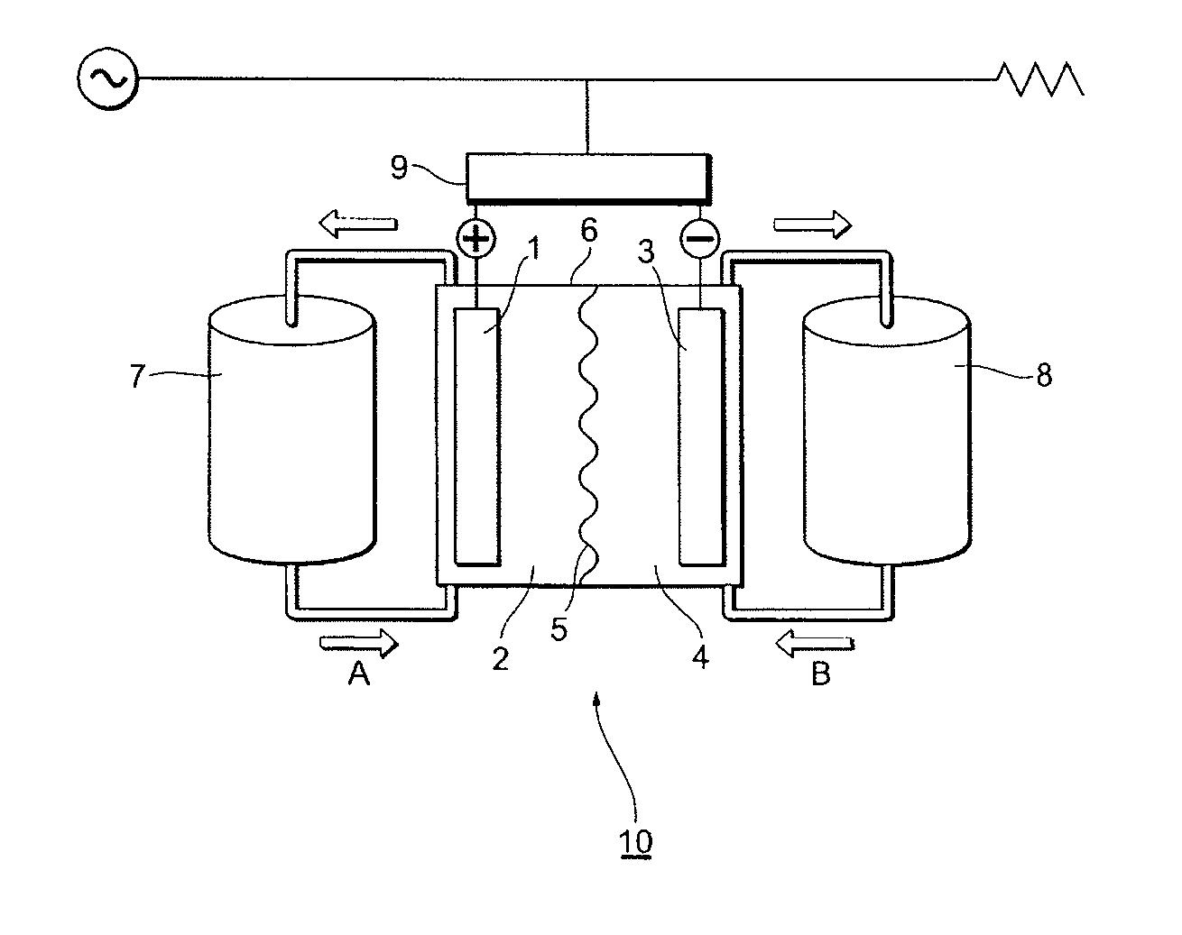
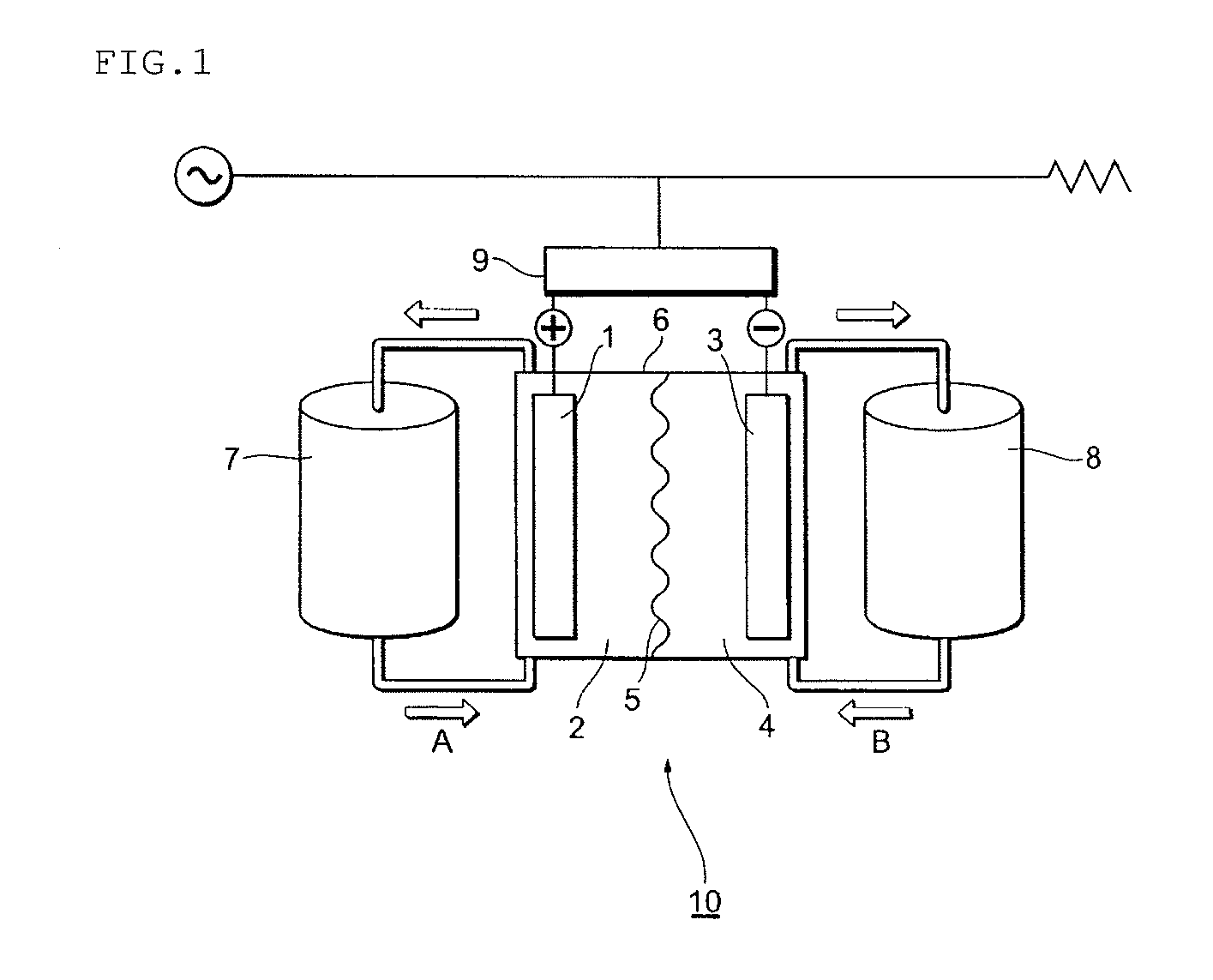
Image

Examples
example 1
(1) Fabrication of a PFSA Resin Precursor
[0315]A 10% aqueous solution of C7F15COONH4 and pure water were charged in a stainless steel-made stirring-type autoclave, and the interior atmosphere of the autoclave was sufficiently vacuum and replaced by nitrogen; and thereafter, tetrafluoroethylene (CF2═CF2) (hereinafter, also referred to as “TFE”) gas was introduced, and the interior pressure was pressurized to 0.7 MPa in terms of gage pressure.
[0316]Then, an ammonium persulfuric acid aqueous solution was injected to initiate the polymerization.
[0317]While in order to replenish TFE consumed by the polymerization, TFE gas was continuously fed so as to hold the pressure of the autoclave at 0.7 MPa, CF2═CFO(CF2)2—SO2F of an amount corresponding to 0.70 times the amount of TFE fed in mass ratio was continuously fed to carry out the polymerization by regulating the polymerization condition in a best range to thereby obtain a perfluorocarbonsulfonic acid (PFSA) resin precursor powder.
[0318]Th...
example 2
(1) Production of a PTFE Microporous Membrane 2
[0343]300 mL of a hydrocarbon oil as an extrusion liquid lubricating oil was added to and mixed with 1 kg of a PTFE fine powder having a number-average molecular weight of 12,000,000, at 20° C.
[0344]Then, a round bar-shape molded body obtained by paste-extruding the mixture was formed into a film-shape by a calender roll heated to 70° C. to thereby obtain a PTFE film. The film was passed through a hot air drying oven at 250° C. to evaporate and remove the extrusion aid to thereby obtain an unbaked film having an average thickness of 200 μm and an average width of 280 mm.
[0345]Then, the unbaked PTFE film was stretched at a stretch ratio of 5 times in the longitudinal direction (MD direction), and taken up.
[0346]Both edges of the obtained MD-direction-stretched PTFE film were pinched by clips; and the film was stretched at a stretch ratio of 5 times in the width direction (TD direction), and subjected to heat setting to thereby obtain a s...
example 3
(1) Production of a PTFE Microporous Membrane 3
[0352]A microporous membrane (the distribution center of the pore distribution was 0.2 μm) of 8 μm in thickness was produced by the similar method as for the PTFE microporous membrane 2, and made a PTFE microporous membrane 3, except for stretching at a stretch ratio of 15 times in the longitudinal direction (MD direction) and a stretch ratio of 8 times in the width direction (TD direction).
(2) Production of an Electrolyte Membrane
[0353]An electrolyte membrane was obtained by the similar method as in Example 1, except for using the PTFE microporous membrane 3.
[0354]The equilibrium moisture content of the obtained electrolyte membrane was 12% by mass, and the maximum moisture content thereof in water at 25° C. for 3 hours was 23% by mass.
[0355]The plane-direction dimensional change of the obtained electrolyte membrane was measured, and was 8%, which was a small dimensional change.
[0356]As a result of carrying out a charge and discharge t...
PUM
| Property | Measurement | Unit |
|---|---|---|
| Temperature | aaaaa | aaaaa |
| Time | aaaaa | aaaaa |
| Percent by mass | aaaaa | aaaaa |
Abstract
Description
Claims
Application Information