Method for manufacturing conductive member, conductive member, and touch panel using same

a technology of conductive components and touch panels, which is applied in the direction of conductive layers on insulating supports, liquid/solution decomposition chemical coatings, instruments, etc., can solve the problems of inapplicability of the method to a conductive film, difficult to put into practical use of energy rays, and failure to achieve the effect of insulating failure from electrochemical migration, favorable conductive properties, and high transparency

Active Publication Date: 2015-01-08
FUJIFILM CORP
View PDF3 Cites 29 Cited by
  • Summary
  • Abstract
  • Description
  • Claims
  • Application Information

AI Technical Summary

Benefits of technology

[0013]As a result of intensive studies based on the above-described object, the inventors found that it is preferable to form a light-scattering layer provided with insulating light-scattering fine particles (hereinafter also referred to as “non-conductive light-scattering fine particles” or simply “light-scattering fine particles”) in non-conductive regions to decrease the haze difference between conductive regions including metal nanowires and the non-conductive regions including no metal nanowires. In addition, the inventors unexpectedly found that the above-described configuration suppresses the occurrence of migration, and completed the invention.
[0038]According to the invention, it is possible to provide a conductive member that has favorable conductive properties and high transparency, and does not easily allow the appearance of a pattern and insulation failure caused by electrochemical migration, a method for manufacturing the same, and a touch panel and a display apparatus in which the conductive member is used.

Problems solved by technology
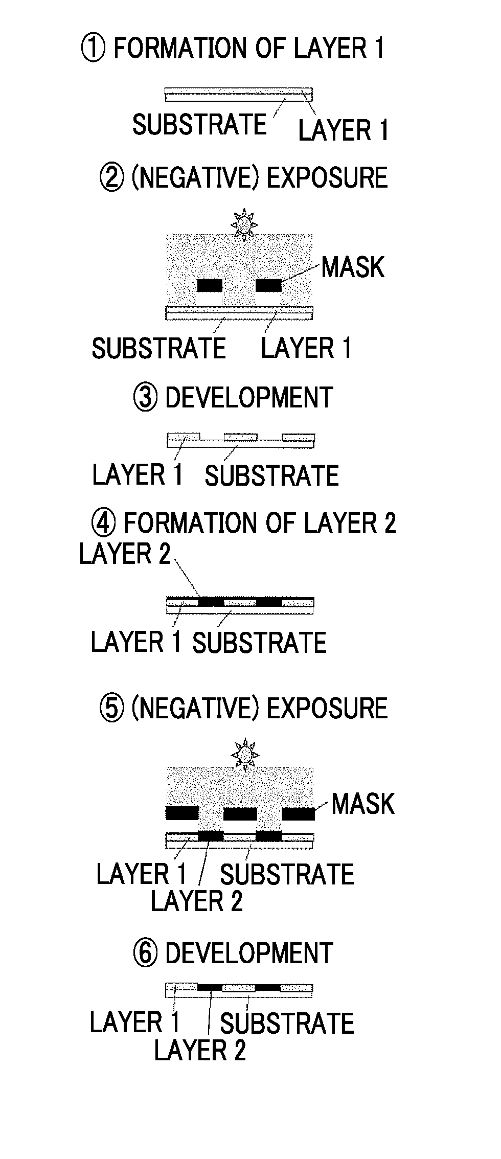
The method of JP2010-157400A in which an energy ray is used is difficult to be put into practical use since the costs for a facility and energy for the pattern radiation of an energy ray are high.
Furthermore, JP2010-287540A is intended to supply environment resistance such as oxidizing resistance or sulfurizing resistance and thermal resistance, and there was a problem in that the method is not applicable to a conductive film obtained by applying a corrosion inhibitor to a conductive fiber or to a conductive film formed so that only a part of a conductive fiber is exposed on the film surface, and the majority is implanted in the film.
As a result of intensive studies regarding the techniques described in the above-described documents, the present inventors found that, compared with a case in which conductive particles are fully removed, the above-described techniques are likely to cause insulation failure from electrochemical migration (hereinafter, also referred to simply as migration).
However, when conductive particles are fully removed, the problem of haze still remains.

Method used


Image

  • Method for manufacturing conductive member, conductive member, and touch panel using same
  • Method for manufacturing conductive member, conductive member, and touch panel using same
  • Method for manufacturing conductive member, conductive member, and touch panel using same

Examples


preparation example 1

The Preparation of a Silver Nanowire Dispersion Liquid (1)

[0337]The following addition liquids A, B, C, and D were prepared in advance.

[0338][Addition Liquid A]

[0339]120 mg of stearyl trimethyl ammonium chloride, 600 mg of strearyl trimethyl ammonium hydroxide, and 2.0 g of glucose were dissolved in 120.0 g of distilled water, thereby preparing a reaction solution A-1. Furthermore, 70 mg of silver nitrate powder were dissolved in 2.0 g of distilled water, thereby preparing a silver nitrate aqueous solution A-1. The reaction solution A-1 was held at 25° C., and the silver nitrate aqueous solution A-1 was added under fast stirring. The fast stirring was continued over 180 minutes from the addition of the silver nitrate aqueous solution A-1, thereby preparing an addition liquid A.

[0340][Addition Liquid B]

[0341]42.0 g of silver nitrate powder was dissolved in 958 g of distilled water.

[0342][Addition Liquid C]

[0343]75 g of 25% ammonia water was mixed with 925 g of distilled water

[0344][A...

preparation example 2

The Preparation of a Silver Nanowire Dispersion Liquid (2)

[0351]60 g of silver nitrate powder was dissolved in 370 g of propylene glycol, thereby preparing a silver nitrate solution 101. 72.0 g of polyvinyl pyrrolidone (molecular weight of 55,000) was added to 4.45 kg of propylene glycol, and the mixture was heated to 90° C. while ventilating nitrogen gas through a gas-phase section of a container. The liquid was used as a reaction solution 101. While holding the ventilation of the nitrogen gas, 2.50 g of the silver nitrate solution 101 was added to the reaction solution 101 under fast stirring, and heating and stirring was carried out over one minute. Furthermore, the solution was added to a solution obtained by dissolving 11.8 g of tetrabutyl ammonium chloride to 100 g of propylene glycol, thereby preparing a reaction solution 202.

[0352]200 g of the silver nitrate solution 101 was added to a reaction solution 202 being held at 90° C. and stirred at a stirring rate of 500 rpm at an...

preparation example 3

The Preparation of a Silver Nanowire Dispersion Liquid (3)

[0356]A silver nanowire dispersion liquid (3) having a metal content of 0.45% was obtained in the same manner as in Preparation Example 1 except for the fact that the addition liquid A was not used in Preparation Example 1.

[0357]Regarding silver nanowires in the obtained silver nanowire dispersion liquid (3), the average short axis length, the average long axis length, the variation coefficient of the short axis length of the silver nanowires, and the average aspect ratio were measured as described above.

[0358]As a result, the average short axis length was 47.2 nm, the average long axis length was 12.6 μm, and the variation coefficient was 23.1%. The average aspect ratio was 267. Hereinafter, the“silver nanowire dispersion liquid (3)” denoted below will refer to the silver nanowire dispersion liquid obtained using the above-described method.


PUM

PropertyMeasurementUnit
lengthaaaaaaaaaa
lengthaaaaaaaaaa
conductiveaaaaaaaaaa

Abstract

A method for manufacturing of a conductive member includeforming one of a conductive layer including metal nanowires or a light-scattering layer including insulating light-scattering fine particles on a substrate in a pattern shape; andforming the other of the conductive layer including metal nanowires or the light-scattering layer including insulating light-scattering fine particles on a space of the substrate wherein the one of the conductive layer or the light-scattering layer is not formed.

Description

CROSS-REFERENCE TO RELATED APPLICATIONS[0001]This application is a Continuation of PCT International Application No. PCT / JP2013 / 055334 filed on Feb. 28, 2013, which claims priority under 35 U.S.C §119(a) to Japanese Patent Application No. 2013-015147 filed on Jan. 30, 2013 and Japanese Patent Application No. 2012-066920 filed on Mar. 23, 2012. Each of the above application(s) is hereby expressly incorporated by reference, in its entirety, into the present application.BACKGROUND OF THE INVENTION[0002]1. Field of the Invention[0003]The present invention relates to a method for manufacturing a conductive member, a conductive member, and a touch panel using the same.[0004]2. Description of the Related Art[0005]While ITO is widely used as a conductive material for an electrode which is used for a display apparatus such as a touch panel-equipped liquid crystal display or an organic EL display (for example, a handheld terminal and a mobile phone), an integrated solar cell, and the like, th...

Claims


Application Information

Patent Timeline
Patent Type & Authority Applications(United States)
IPC IPC(8): G02B5/02G02F1/1343G02F1/1335G02F1/1333
CPCG02B5/0242G02F1/13338G02F1/13439G02F2001/133541G02F1/133528G02B5/0268G02F1/133504G06F2203/04103H05K3/06H05K1/0274H05K2201/0108H05K2201/09881H05K2203/0571C23C18/08G06F3/045G06F3/0445H10K50/81H10K50/854H01B5/14H01B13/00G06F3/0448G06F3/041G02F1/133541
Inventor KATAGIRI, KENSUKE
Owner FUJIFILM CORP
Why Eureka
Try Eureka