Novel organic electroluminescent compounds and organic electroluminescent device comprising the same

a technology of organic electroluminescent compounds and organic electroluminescent devices, which is applied in the direction of luminescent compositions, organic chemistry, anthracene dyes, etc., can solve the problems of short operating lifespan, low quantum efficiency of organic el devices, and inability to achieve good luminous efficiency, long driving lifespan, and high luminous efficiency

Inactive Publication Date: 2015-04-16
MITSUBISHI ELECTRIC RES LAB INC
View PDF2 Cites 12 Cited by
  • Summary
  • Abstract
  • Description
  • Claims
  • Application Information

AI Technical Summary

Benefits of technology

[0025]The organic electroluminescent compounds according to the present invention have advantages in that they have high luminous efficiency and a long operating lifespan, and thus can produce an organic electroluminescent device having a long driving lifespan. Further, the organic electroluminescent compounds according to the present can be used as a phosphorescent host material, a hole transport material, or mixed host materials; have the superior ability of hole transport; prevent crystallization in the production of the device; are suitable for forming a layer; and improve the current density of the device thereby reducing driving voltage of the device.EMBODIMENTS OF THE INVENTION
[0026]Hereinafter, the present invention will be described in detail. However, the following description is intended to explain the invention, and is not meant in any way to restrict the scope of the invention.
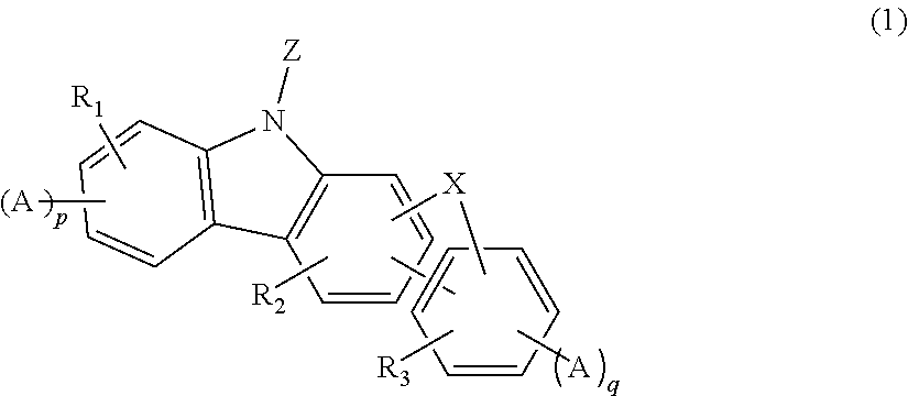
[0027]The present invention relates to an organic electroluminescent compound represented by formula 1 above, an organic electroluminescent material comprising the organic electroluminescent compound, and an organic electroluminescent device comprising the material.
[0028]Herein, “(C1-C30)alkyl(ene)” is meant to be a linear or branched alkyl(ene) having 1 to 30 carbon atoms, in which the number of carbon atoms is preferably 1 to 20, more preferably 1 to 10, and includes methyl, ethyl, n-propyl, isopropyl, n-butyl, isobutyl, tert-butyl, etc. “(C2-C30) alkenyl” is meant to be a linear or branched alkenyl having 2 to 30 carbon atoms, in which the number of carbon atoms is preferably 2 to 20, more preferably 2 to 10, and includes vinyl, 1-propenyl, 2-propenyl, 1-butenyl, 2-butenyl, 3-butenyl, 2-methylbut-2-enyl, etc. “(C2-C30)alkynyl” is a linear or branched alkynyl having 2 to 30 carbon atoms, in which the number of carbon atoms is preferably 2 to 20, more preferably 2 to 10, and includes ethynyl, 1-propynyl, 2-propynyl, 1-butynyl, 2-butynyl, 3-butynyl, 1-methylpent-2-ynyl, etc. “(C3-C30)cycloalkyl” is a mono- or polycyclic hydrocarbon having 3 to 30 carbon atoms, in which the number of carbon atoms is preferably 3 to 20, more preferably 3 to 7, and includes cyclopropyl, cyclobutyl, cyclopentyl, cyclohexyl, etc. “3- to 7-membered heterocycloalkyl” is a cycloalkyl having at least one heteroatom selected from B, N, O, S, P(═O), Si and P, preferably O, S and N, and 3 to 7, preferably 5 to 7 ring backbone atoms, and includes tetrahydrofurane, pyrrolidine, thiolan, tetrahydropyran, etc. “(C6-C30)aryl(ene)” is a monocyclic or fused ring derived from an aromatic hydrocarbon having 6 to 30 carbon atoms, in which the number of carbon atoms is preferably 6 to 20, more preferably 6 to 15, and includes phenyl, biphenyl, terphenyl, naphthyl, fluorenyl, phenanthrenyl, anthracenyl, indenyl, triphenylenyl, pyrenyl, tetracenyl, perylenyl, chrysenyl, naphthacenyl, fluoranthenyl, etc. “5- to 30-membered heteroaryl(ene)” is an aryl group having at least one, preferably 1 to 4 heteroatom selected from the group consisting of B, N, O, S, P(═O), Si and P, and 5 to 30 ring backbone atoms; is a monocyclic ring, or a fused ring condensed with at least one benzene ring; has preferably 5 to 20, more preferably 5 to 15 ring backbone atoms; may be partially saturated; may be one formed by linking at least one heteroaryl or aryl group to a heteroaryl group via a single bond(s); and includes a monocyclic ring-type heteroaryl including furyl, thiophenyl, pyrrolyl, imidazolyl, pyrazolyl, thiazolyl, thiadiazolyl, isothiazolyl, isoxazolyl, oxazolyl, oxadiazolyl, triazinyl, tetrazinyl, triazolyl, tetrazolyl, furazanyl, pyridyl, pyrazinyl, pyrimidinyl, pyridazinyl, etc., and a fused ring-type heteroaryl including benzofuranyl, benzothiophenyl, isobenzofuranyl, dibenzofuranyl, dibenzothiophenyl, benzoimidazolyl, benzothiazolyl, benzoisothiazolyl, benzoisoxazolyl, benzoxazolyl, isoindolyl, indolyl, indazolyl, benzothiadiazolyl, quinolyl, isoquinolyl, cinnolinyl, quinazolinyl, quinoxalinyl, carbazolyl, phenoxazinyl, phenanthridinyl, benzodioxolyl, etc. Further, “halogen” includes F, Cl, Br and I.
[0029]Herein, “substituted” in the expression “substituted or unsubstituted” means that a hydrogen atom in a certain functional group is replaced with another atom or group, i.e., a substituent.
[0030]Substituents of the substituted alkyl group, the substituted aryl(ene) group, and the substituted heteroaryl(ene) group in L1, L2, Ar1, and R1 to R15 groups of formulae 1 to 3, each independently are at least one selected from the group consisting of deuterium; a halogen; a cyano group; a carboxyl group; a nitro group; a hydroxyl group; a (C1-C30)alkyl group; a halo(C1-C30)alkyl group; a (C6-C30)aryl group; a 5- to 30-membered heteroaryl group; a 5- to 30-membered heteroaryl group substituted with a (C6-C30)aryl; a (C6-C30)aryl group substituted with a 5- to 30-membered heteroaryl; a (C3-C30)cycloalkyl group; a 3- to 7-membered heterocycloalkyl group; a tri(C1-C30)alkylsilyl group; a tri(C6-C30)arylsilyl group; a di(C1-C30)alkyl(C6-C30)arylsilyl group; a (C1-C30)alkyldi(C6-C30)arylsilyl group; a (C2-C30)alkenyl group; a (C2-C30)alkynyl group; a mono- or di(C1-C30)alkylamino group; a mono- or di(C6-C30)arylamino group; a (C1-C30)alkyl(C6-C30)arylamino group; a di(C6-C30)arylboronyl group; a di(C1-C30)alkylboronyl group; a (C1-C30)alkyl(C6-C30)arylboronyl group; a (C6-C30)aryl(C1-C30)alkyl group; and a (C1-C30)alkyl(C6-C30)aryl group.

Problems solved by technology

Though these phosphorescent host materials provide good light-emitting characteristics, they have the following disadvantages: (1) Due to their low glass transition temperatures and poor thermal stability, their degradation may occur during a high-temperature deposition process in a vacuum.
Thus, the EL device using conventional phosphorescent materials has no advantage in terms of power efficiency (Im / W).
(3) Further, the operating lifespan and luminous efficiency of the organic EL device are not satisfactory.
However, the organic EL device comprising the materials has low quantum efficiency and a short operating lifespan, because, when the organic EL device is driven at a high current, thermal stress is generated between an anode and a hole injection layer, thereby rapidly reducing the operating lifespan of the device.
Further, holes greatly move in organic materials used in a hole injection layer, and thus the hole-electron charge balance is broken and quantum efficiency (cd / A) is reduced.
However, organic EL devices comprising the compounds of the publications are not satisfactory in power efficiency, luminous efficiency, quantum efficiency, and operating lifespan.

Method used


Image

  • Novel organic electroluminescent compounds and organic electroluminescent device comprising the same
  • Novel organic electroluminescent compounds and organic electroluminescent device comprising the same
  • Novel organic electroluminescent compounds and organic electroluminescent device comprising the same

Examples


example 1

Device Example 1

Production of an OLED Device Using the Organic Electroluminescent Compound According to the Present Invention

[0113]An OLED device was produced using the organic electroluminescent compound according to the present invention. A transparent electrode indium tin oxide (ITO) thin film (15 Ω / sq) on a glass substrate for an organic light-emitting diode (OLED) device (Samsung Corning, Republic of Korea) was subjected to an ultrasonic washing with trichloroethylene, acetone, ethanol, and distilled water, sequentially, and then was stored in isopropanol. Then, the ITO substrate was mounted on a substrate holder of a vacuum vapor depositing apparatus. N1,N1′-([1,1′-biphenyl]-4,4′-diyl)bis(N1-(naphthalene-1-yl)-N4,N4-diphenylbenzene-1,4-diamine) was introduced into a cell of the vacuum vapor depositing apparatus, and then the pressure in the chamber of the apparatus was controlled to 10−6 torr. Thereafter, an electric current was applied to the cell to evaporate the above intro...

example 2

Device Example 2

Production of an OLED Device Using the Organic Electroluminescent Compound According to the Present Invention

[0115]An OLED device was produced in the same manner as in Device Example 1, except for using compound C-10 as the hole transport layer, 9-phenyl-10-(4-phenylnaphthalene-1-yl)anthracene as a host, and (E)-9,9-dimethyl-7-(4-(naphthalene-2-yl(phenyl)amino)styryl)-N,N-diphenyl-9H-fluorene-2-amine as a dopant.

[0116]The produced OLED device showed blue emission having a luminance of 2050 cd / m2 and a current density of 28.5 mA / cm2.

example 3

Device Example 3

Production of an OLED Device Using the Organic Electroluminescent Compound According to the Present Invention

[0117]An OLED device was produced in the same manner as in Device Example 1, except for using compound C-11 as the hole transport layer.

[0118]The produced OLED device showed green emission having a luminance of 4000 cd / m2 and a current density of 7.4 mA / cm2.


PUM


Abstract

The present invention relates to novel organic electroluminescent compounds and an organic electroluminescent device containing the same. The organic electroluminescent compounds according to the present invention can be used as a phosphorescent host material, a hole transport material, or a mixed host material; have a good hole transport ability; prevent crystallization in the production of the device; are suitable for forming a layer; and improve the current density of the device thereby reducing the driving voltage of the device.

Description

TECHNICAL FIELD[0001]The present invention relates to novel organic electroluminescent compounds and organic electroluminescent device comprising the same.BACKGROUND ART[0002]An electroluminescent (EL) device is a self-light-emitting device with the advantage of providing a wider viewing angle, a greater contrast ratio, and a faster response time. An organic EL device was first developed by Eastman Kodak, by using small aromatic diamine molecules, and aluminum complexes as a material for forming a light-emitting layer [Appl. Phys. Lett. 51, 913, 1987].[0003]The most important factor determining luminous efficiency in an organic EL device is the light-emitting material. Until now, fluorescent materials have been widely used as light-emitting materials. However, in view of electroluminescent mechanisms, developing phosphorescent materials is one of the best methods to theoretically enhance luminous efficiency by four (4) times compared to fluorescent materials. Iridium(III) complexes ...

Claims


Application Information

Patent Timeline
Patent Type & Authority Applications(United States)
IPC IPC(8): H01L51/00
CPCC07F7/0812C09B57/00C07D405/10C07D409/04C07D409/10C07D409/14H01L51/0071H01L51/0072H01L51/5012C07D487/04C07D491/048C07D495/04C07D209/94C07D209/96C07D405/14C09K11/06H10K85/657H10K85/6572H10K50/11
Inventor AHN, HEE-CHOONCHO, YOUNG-JUNKIM, BONG-OKKIM, YONG-GILKWON, HYUCK-JOOKU, JONG-SEOKLEE, HYO-JUNGLEE, KYUNG-JOOLEE, TAE-JINYANG, JEONG-EUN
Owner MITSUBISHI ELECTRIC RES LAB INC
Why Eureka
Try Eureka