Smart grid power converter

a power converter and smart grid technology, applied in the direction of dc-dc conversion, climate sustainability, power electronics conversion, etc., can solve the problems of increasing costs and losses, reducing reliability, and reducing so as to reduce the size of magnetic components, reduce the effect of magnetic components and minimal impact on the performance of power converters

Active Publication Date: 2015-04-23
GARRITY POWER SERVICES
View PDF6 Cites 19 Cited by
  • Summary
  • Abstract
  • Description
  • Claims
  • Application Information

AI Technical Summary

Benefits of technology

[0017]The preferred embodiment described above reduces the size of the magnetic components with minimal impact on the performance of the power converter.
[0018]A further preferred embodiment of the present invention comprises a controller that provides a first signal and a second signal. The first signal and second signal are rectified sinusoids with a DC offset and are in phase with each other such that the amplitude of the first signal is less than or equal to the amplitude of the second signal and the sinusoidal portion of the second signal divided by the sinusoidal portion of the first signal is a constant over the course of each half-cycle of the AC output. Furthermore, the second controller compares the current flowing in the AC bridge comprised of controllable semiconductor switches three, four, five, and six to the first signal and the second signal to determine whether to turn on any of those switches in such a way as to either

Problems solved by technology

If the switches and diode are rated for 650V to keep costs down and obtain parts with low ohmic losses, the operating voltage margins will be quite small, particularly over the large temperature ranges typically seen by photovoltaic inverters, and this will result in reduced reliability.
If the components are rated for more than 650V, costs and losses will increase.
Furthermore, any increases to the input voltage range to accommodate a variety of photovoltaic module designs will cause additional impact to the design of the switching and silicon diode

Method used


Image

  • Smart grid power converter
  • Smart grid power converter
  • Smart grid power converter

Examples


Embodiment Construction

Prior Art

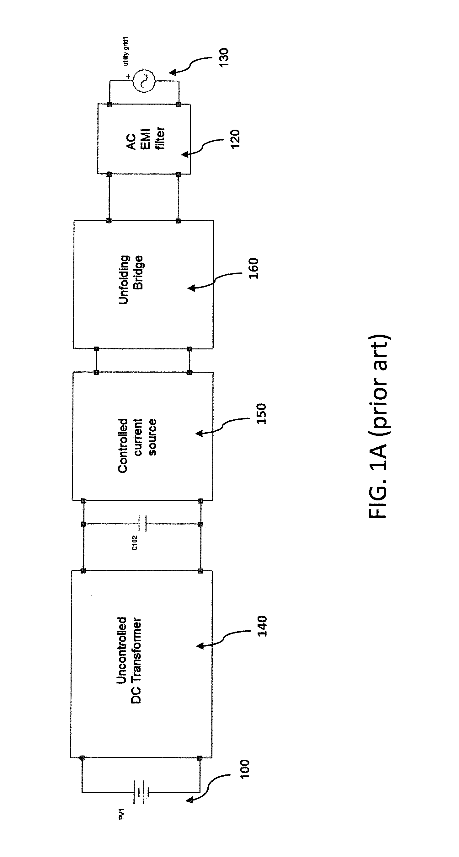
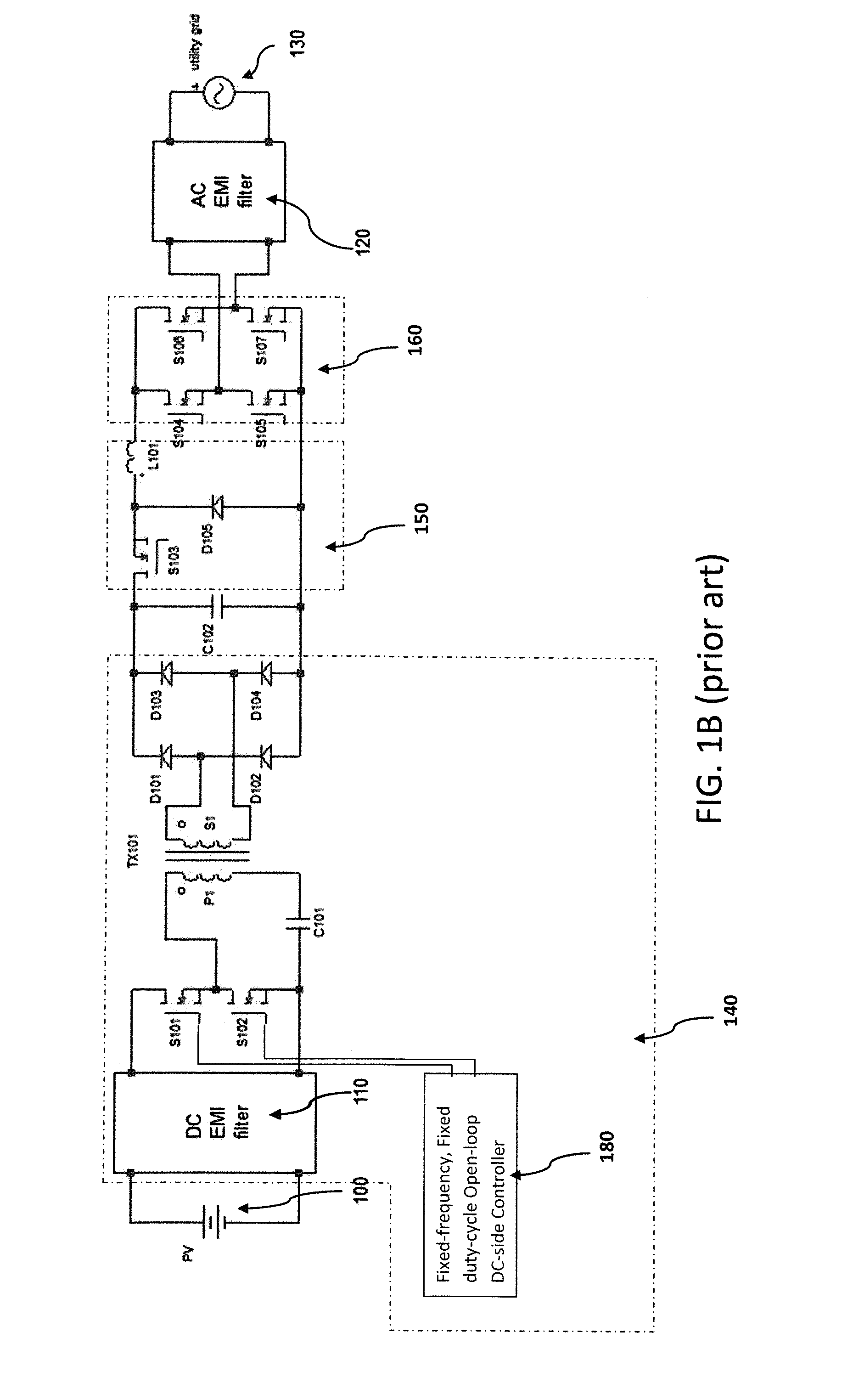
[0035]FIG. 1A shows a block diagram and FIG. 1B shows a basic circuit of a prior art micro-inverter. The converter has three stages. The first stage 140 is a DC-DC transformer that is composed of an LLC resonant converter operating at a fixed frequency that is equal to its upper resonant frequency. The second stage 150 is a controlled current source that is composed of a high-voltage buck converter without the output capacitor and which produces a full-wave rectified sinusoidal output current that is in phase with the grid. The third stage 160 is an unfolding bridge that is composed of a MOSFET full-bridge that switches at grid frequency (i.e. 50 Hz or 60 Hz) to change the current sourced by second stage 150 into a full sinusoid.

[0036]The DC transformer consists of Switches S101 and S102, controller 180, capacitor C101, transformer T101 which contains a leakage inductance (not shown), diode bridge D101, D102, D103, and D104, and DC bus cap C102. Bus cap C102 is a non-electr...


PUM


Abstract

A DC-to-AC power converter is disclosed. The power converter has a DC input to receive DC power from a photovoltaic device, an AC output configured for direct connection to an AC mains power supply line, six semiconductor switches, one isolated high-frequency power transformer, two high-frequency inductors, a small resonant capacitor, and a large non-electrolytic (e.g. film) capacitor energy storage component. One of the semiconductor switches located on the primary side of the transformer operates to regulate the voltage across the non-electrolytic capacitor energy storage component. A second semiconductor switch located on the primary side of the transformer provides a resonant reset for the energy stored in the transformer and allows the first semiconductor switch to operate with nearly zero-voltage-switching. The other four semiconductor switches and a high-frequency inductor coupled to the ac output operate with a variable switching frequency to produce a sinusoidal current into the ac output such that the sinusoidal current may be either in phase or out of phase with the ac output voltage.

Description

PRIORITY ENTITLEMENT[0001]This non-provisional application claims priority to U.S. Provisional Patent Application Ser. No. 61 / 887,863 filed on Oct. 7, 2013, entitled “SMART GRID MICROINVERTER,” which is herein incorporated by reference in its entirety. This application and the Provisional patent application have at least one common inventor.FIELD OF INVENTION[0002]This invention generally relates to DC-to-AC power converters. In particular, this invention relates to photovoltaic grid-connected converters and may be of particular use with micro-inverters.BACKGROUND[0003]Distributed generation is growing at a fast pace as society increases its use of renewable resources such as solar energy. The majority of solar power systems in use at this time make use of multiple polycrystalline silicon photovoltaic panels connected in series which are then connected to a string inverter that pumps the power back into a utility grid. The photovoltaic panels are usually placed in series to provide ...

Claims


Application Information

Patent Timeline
IPC IPC(8): H02M5/458
CPCH02M5/458H02M1/36H02M1/42H02M1/44H02M3/285H02M3/33569Y02E10/56H02M7/797Y02B70/10H02M1/0058H02M1/007H02M1/0043H02M3/33571H02M3/01
Inventor GARRITY, PAULJUNGREIS, AARON
Owner GARRITY POWER SERVICES
Why Eureka
Try Eureka