Fuel Cell System

a fuel cell and system technology, applied in the field of fuel cell systems, can solve problems such as non-pure hydrogen fuel consumption

Inactive Publication Date: 2015-04-30
INTELLIGENT ENERGY LTD
View PDF1 Cites 17 Cited by
  • Summary
  • Abstract
  • Description
  • Claims
  • Application Information

AI Technical Summary

Benefits of technology

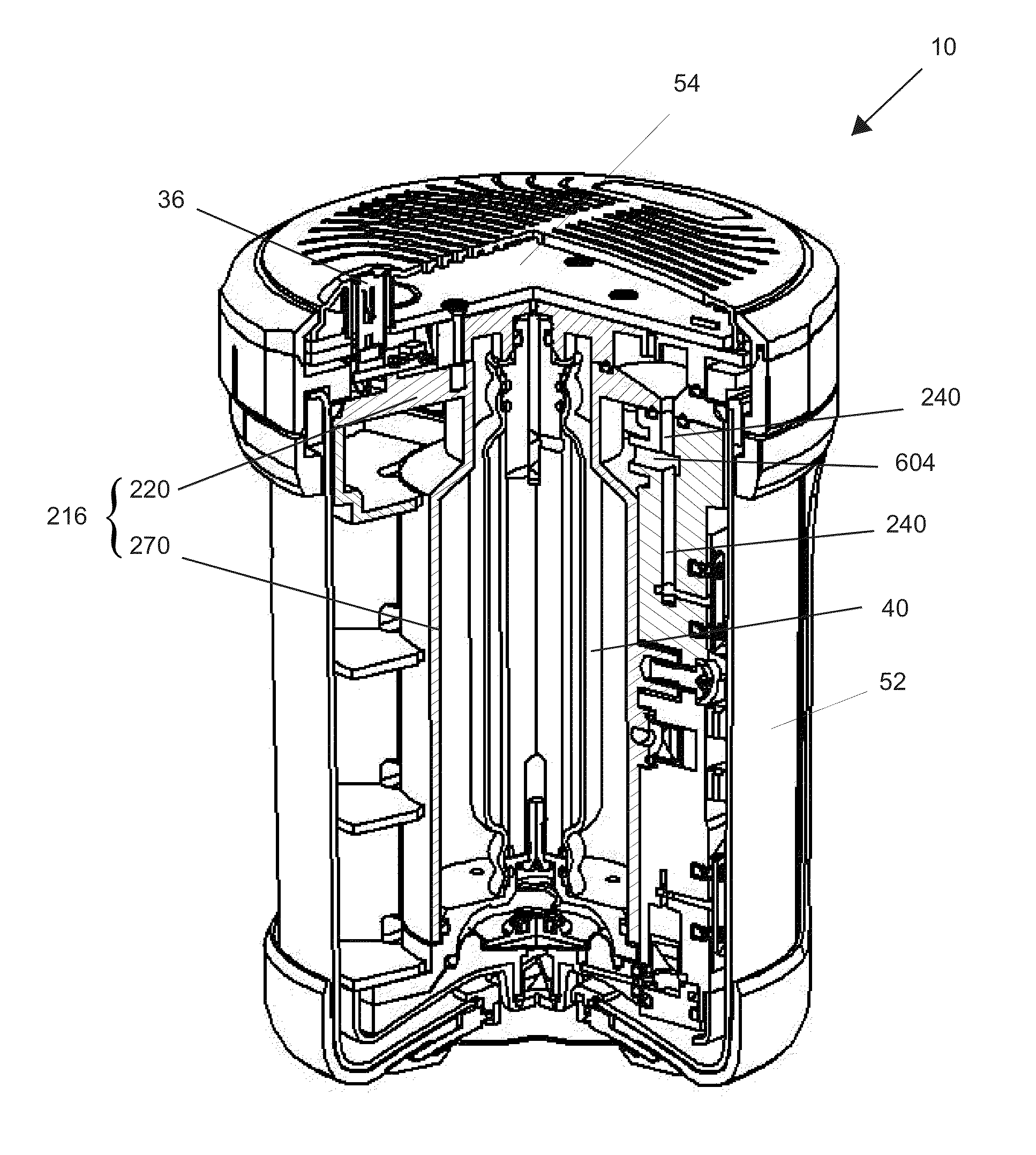
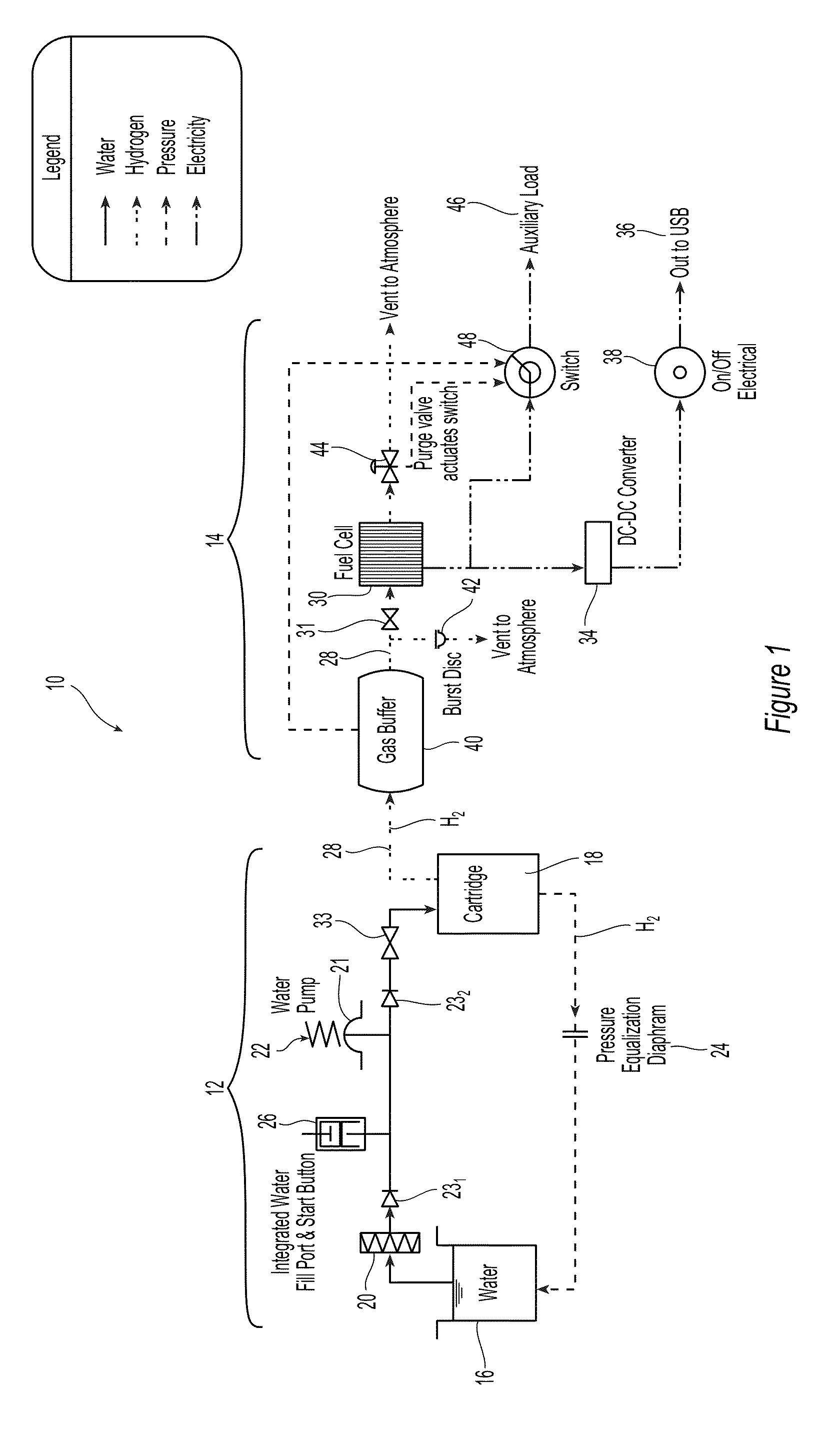
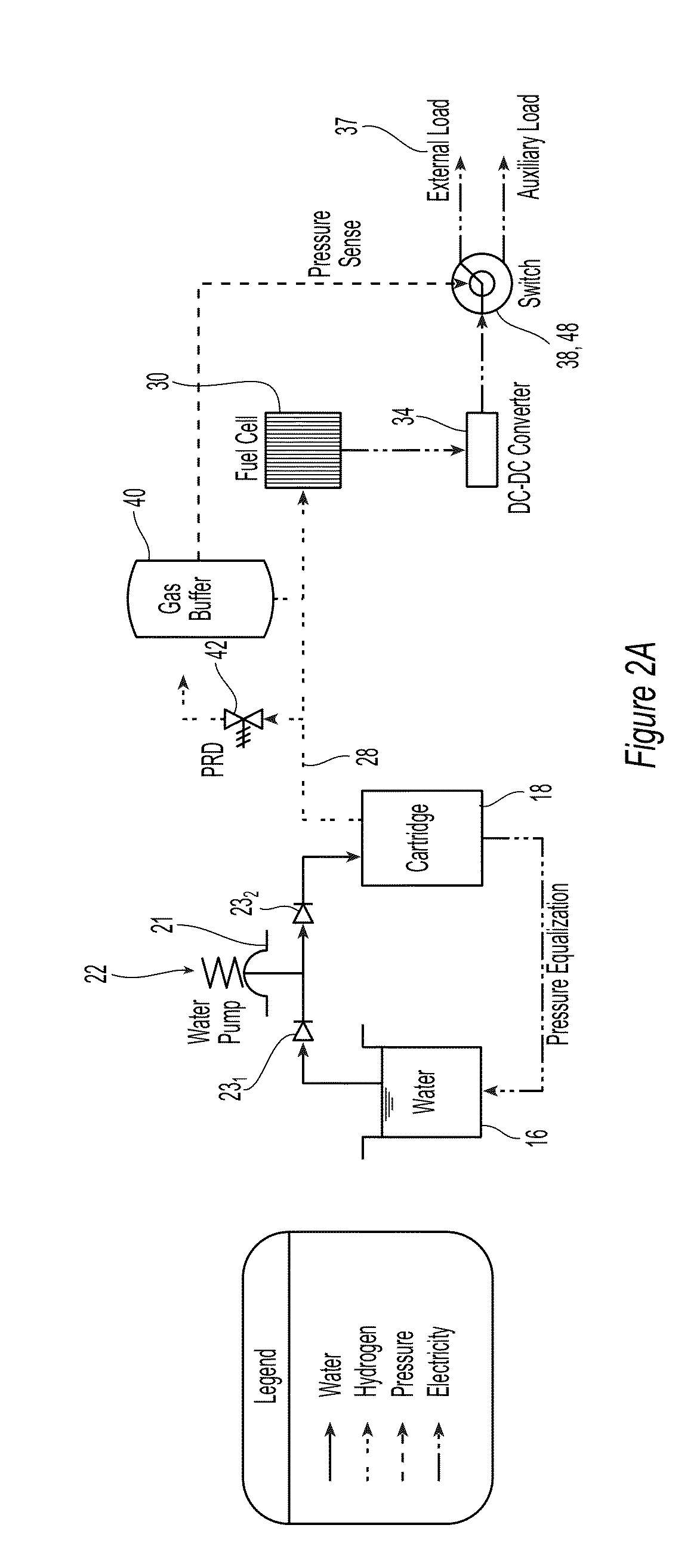
[0014]The fuel cell may also comprise a pressure equalization mechanism that restores or maintains pressure equalization between a first pressure in a reaction chamber containing the solid precursor and a second pressure in the aqueous liquid. The pressure equalization mechanism includes a diaphragm that separates the hydrogen gas in the reaction chamber from the aqueous liquid and that communicates the pressure of the hydrogen gas to the aqueous liquid. This pressure in the aqueous liquid causes a predetermined dose of the aqueous liquid to enter a dose pump. As hydrogen is transported out of the reaction chamber or the fuel cartridge, the pressure within decreases causing said dose in the dose pump to enter t...

Problems solved by technology

Fuel cells generally run on hydrogen (H2) fue...

Method used


Image

  • Fuel Cell System
  • Fuel Cell System
  • Fuel Cell System

Examples


example 1

[0155]

MaterialsPurityParticle SizesMagnesium99%between 40 to 100 mesh(422 microns to 152 micron holes)Iron98%Diameter (microns)4 ≦ 10%10 90% ≦ 45Silicon 98%325 mesh (44 micron holes)

In one preferred embodiment, magnesium particles are first sifted through the coarser mesh, e.g., 40 mesh, to remove the larger particles, and then sifted through the finer mesh, e.g., 100 mesh, to remove the smaller particles leaving behind particles in the range between the holes in the coarser mesh and the holes in the finer mesh. Solid fuels were prepared from 100 parts Mg, 25 parts Fe and 15 parts Si by weight. This mixture was milled in an Attritor mill using ⅜ inch carbon steel sphere grinding media. The milling step was conducted in a nitrogen atmosphere for 15 minutes with a 15 minutes discharge. The milling temperature was less than 38° C. (100° F.) and the nominal particle size is about 110 microns. The resulting particles are hybrid or composite particles of magnesium covered by a fine disper...

example 2

Compositional Affects on Flammability

[0190]FIG. 15 illustrates a bar graph comparing burn rates of some embodiments of the invention. Fuel pellets of the invention were created using various compositions as well as varying amounts of pressure during the pressing process, as indicated along the X-axis. For example, the first composition (furthest to the left on the X-axis) contained 9 parts of a first homogeneous mixture to 1 part secondary material (sodium chloride) and was press formed using a compressive force of thirty thousand pounds. The term “FB500” refers to FIREBRAKE 500, a commercial chemical composition used as a fire retardant material available from U.S. Borax, Inc. of Greenwood Village, Colo. “Blend 1,”“Blend 2,” and “Blend 3” refers to comparable fuel material blends, using magnesium powder. More specifically, Blend 1 comprises magnesium particles in the range of about 175 to about 300 microns, and Blend 2 comprises magnesium particles in the range of about 175 to abou...

example 3

Forming Pellets from Exemplary Chemical Hydride

[0194]A sample fuel pellet was formed comprising calcium hydride and optional silicon. Calcium hydride powder and silicon powder were combined in a turbular mixer in a ratio of about 1 part calcium hydride to 0.28 parts silicon (by weight). The calcium hydride powder was fine enough to pass through a 2 millimeter sieve. The silicon powder had a mesh size of about 325 and a purity of at least 98%. The mixing time was about 30 minutes, the mixing batch size was about 366 grams, and the mixing was conducted at about room temperature. After mixing was complete, the resulting second mixture was pressed into pellets weighing about 2.25 grams using about 35,000 pounds force of pressure. The pellets had a diameter of about 6.6 millimeters.

[0195]In another embodiment of the present invention, solid precursor 18 can be suspended in a suspension agent and formed into slurries or gels and the like. The suspension agent can act as a protective coati...


PUM


Abstract

A complete fuel cell system (10) is described. The fuel cell system (10) comprises at least two fuel precursors (16, 18) that react to create hydrogen. A solid fuel precursor (18) can be carried in disposable fuel cartridges (100). A passive pressure control system including a dose pump (22) and a pressure equalization system (24, 300, 504) is provided to dose a liquid fuel precursor (16) to the solid fuel precursor (18) in the fuel cartridge (100). An outer wall (102) of the fuel cartridge can form a part of the passive pressure control system. The solid fuel precursor may include larger metallic particles coated by another fine metallic particles such that multiple micro galvanic cells are formed on the surface of the larger metallic particles. The fuel cell system may also include a gas buffer (40) that stores produced hydrogen that in unneeded by the fuel cell, and a water trapping mechanism (604). The fuel cell system may also have an electronic vent (46) that consumes unneeded hydrogen.

Description

[0001]The present application claims priority to U.S. provisional patent application entitled “Fuel Cartridge” bearing Ser. No. 61 / 442,043 and filed on 11 Feb. 2011, U.S. provisional patent application entitled “Fuel Pellet for Use in Hydrogen Generation Systems” bearing Ser. No. 61 / 442,104 and filed on 11 Feb. 2011, U.S. provisional patent application entitled “Liquid Dosing Fuel Generator” bearing Ser. No. 61 / 442,130 and filed on 11 Feb. 2011, U.S. provisional patent application entitled “Method and Apparatus for Reducing Hydrogen Venting” bearing Ser. No. 61 / 442,098 and filed on 11 Feb. 2011, and U.S. provisional patent application entitled “Method and Apparatus for Generating Electrical Power from a Chemical Energy Source” bearing Ser. No. 61 / 441,996 and filed on 11 Feb. 2011. All five parent provisional patent applications are incorporated herein by reference in their entireties.FIELD OF THE INVENTION[0002]This invention generally relates to a fuel cell system and in particular...

Claims


Application Information

Patent Timeline
IPC IPC(8): H01M8/06
CPCH01M8/065C01B3/065F17C11/005H01M8/04201H01M8/04208H01M8/04216H01M8/04776H01M8/0656Y02E60/32Y02E60/36Y02E60/50
Inventor MCLEAN, GERARD F.GILL, LAURAIACONIS, JEAN-LOUISSCHROOTEN, JEREMYGURIN, MIKHAILTAM, BENJAMINSEAMAN, SALLYZIMMERMANN, JOERG
Owner INTELLIGENT ENERGY LTD
Why Eureka
Try Eureka