Method and apparatus for automated scanning probe microscopy

Inactive Publication Date: 2015-08-27
NUOMEDIS
View PDF7 Cites 3 Cited by
  • Summary
  • Abstract
  • Description
  • Claims
  • Application Information

AI Technical Summary

Benefits of technology

This patent aims to allow for more efficient and accurate measurements of large, uneven, or three-dimensional samples without requiring human adjustment. It also aims to increase throughput by detecting specific areas of interest on tissue using optical spectral information.

Problems solved by technology

Completely scanning an object of e.g. 1 mm diameter width and 10 mm length is thus obviously a lengthy task, taking altogether between 1'000 and 100'000 scans, each scan requiring a readjustment of the sample.
However, all these procedures are time consuming.
Therein, the main problems addressed are the optimizing of scan parameters and the subsequent processing of measurements using predefined parameter sets.
All efforts so far do not provide an automated method or device for a pre-evaluation of any measurements and automated search for optimized measurement conditions or preferable measurement positions, i.e. positions which promise high yield of good quality results.
However, none of these coarse optical scanning methods provides a resolution of the obtained data that is comparable to the resolution obtainable with an SPM.
Further, none of them is in any way suited for or adapted to an SPM.
First, the method of raster scanning differs fundamentally from optical surface investigation methods.
Second, the obtained data of the two methods are incompatible.
Third, optical scanning apparatuses are so different from raster scanning devices that it requires inventive effort to adapt one to the other.

Method used


Image

  • Method and apparatus for automated scanning probe microscopy
  • Method and apparatus for automated scanning probe microscopy
  • Method and apparatus for automated scanning probe microscopy

Examples


second embodiment

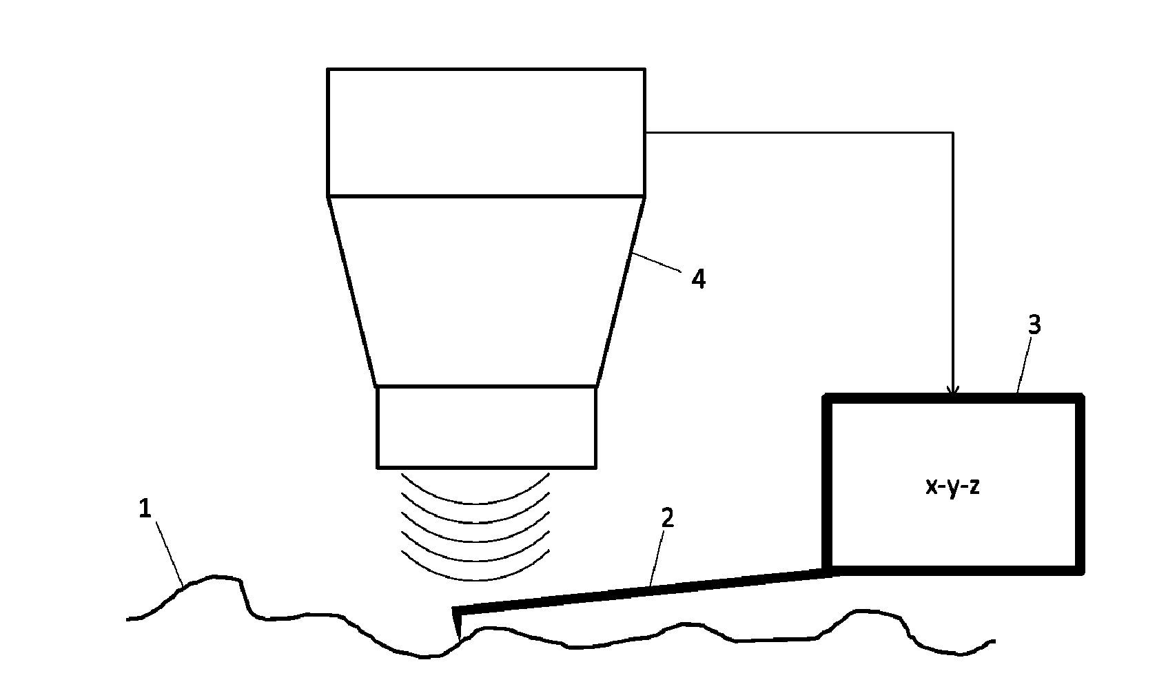
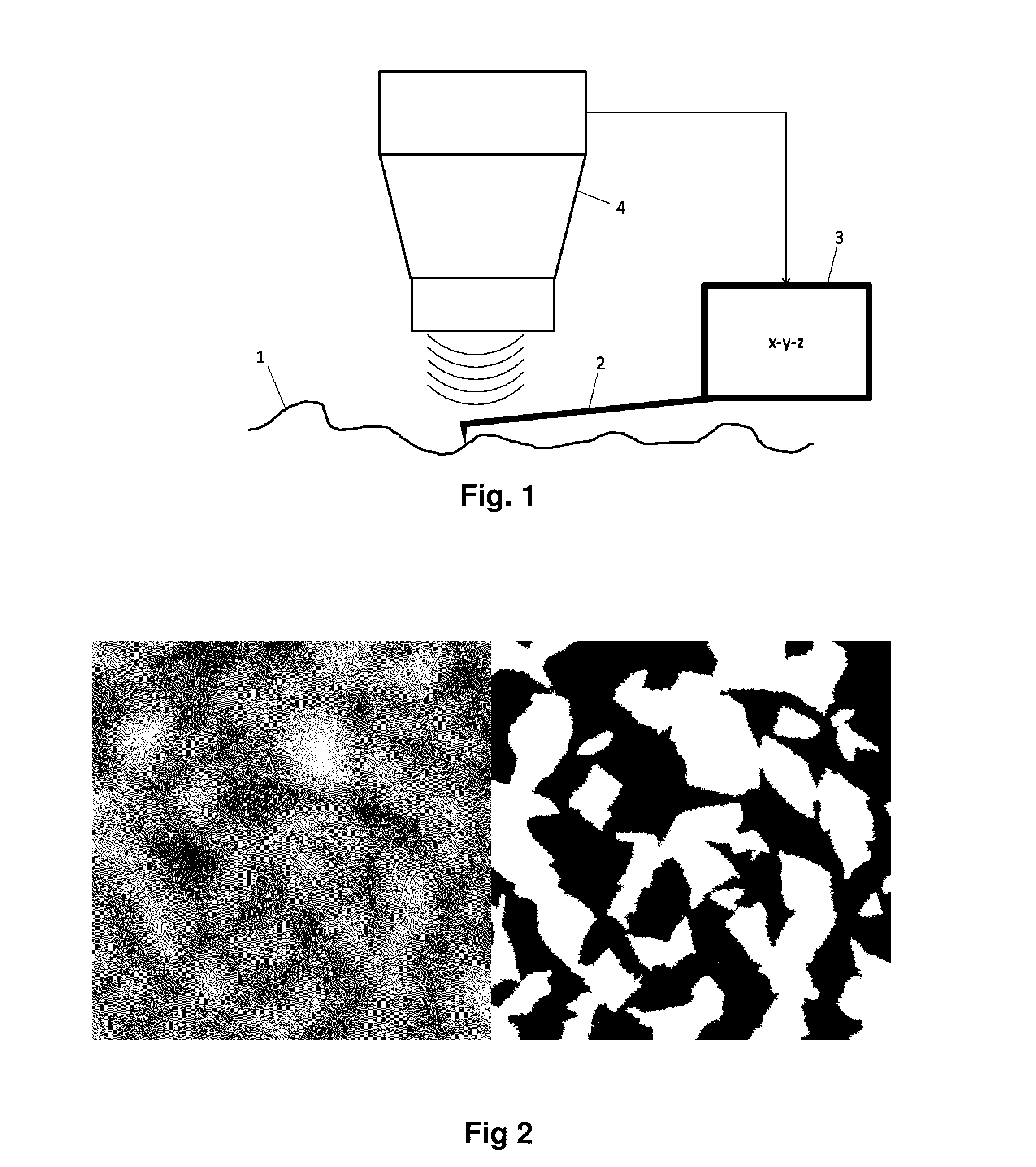
[0041]FIG. 3 shows a second embodiment wherein the PED 14 is a photo-acoustic system whose principle is described by Zhang et al. in Nature Biotechnology 24, No. 7, 848-851 (July 2006): “Functional photoacoustic microscopy for high-resolution and noninvasive in vivo imaging”. In this system, a laser-emitted light pulse is focused onto an object area of a sample and generates photo-acoustic ultrasonic waves. The magnitude of these acoustic waves indicates the distribution of optical energy in the sample. The acoustic waves emitted by the sample are received by an ultrasonic transducer which is scanned in x-y direction across the surface and whose output is processed electronically to generate a digital image of the object area, i.e. an overall or integral map.

[0042]The digital data thus generated by the PED 4 are processed in the same manner as described above to define the areas of interest of the sample. These locations can be single points or coherent areas. The SPM probe is then ...

third embodiment

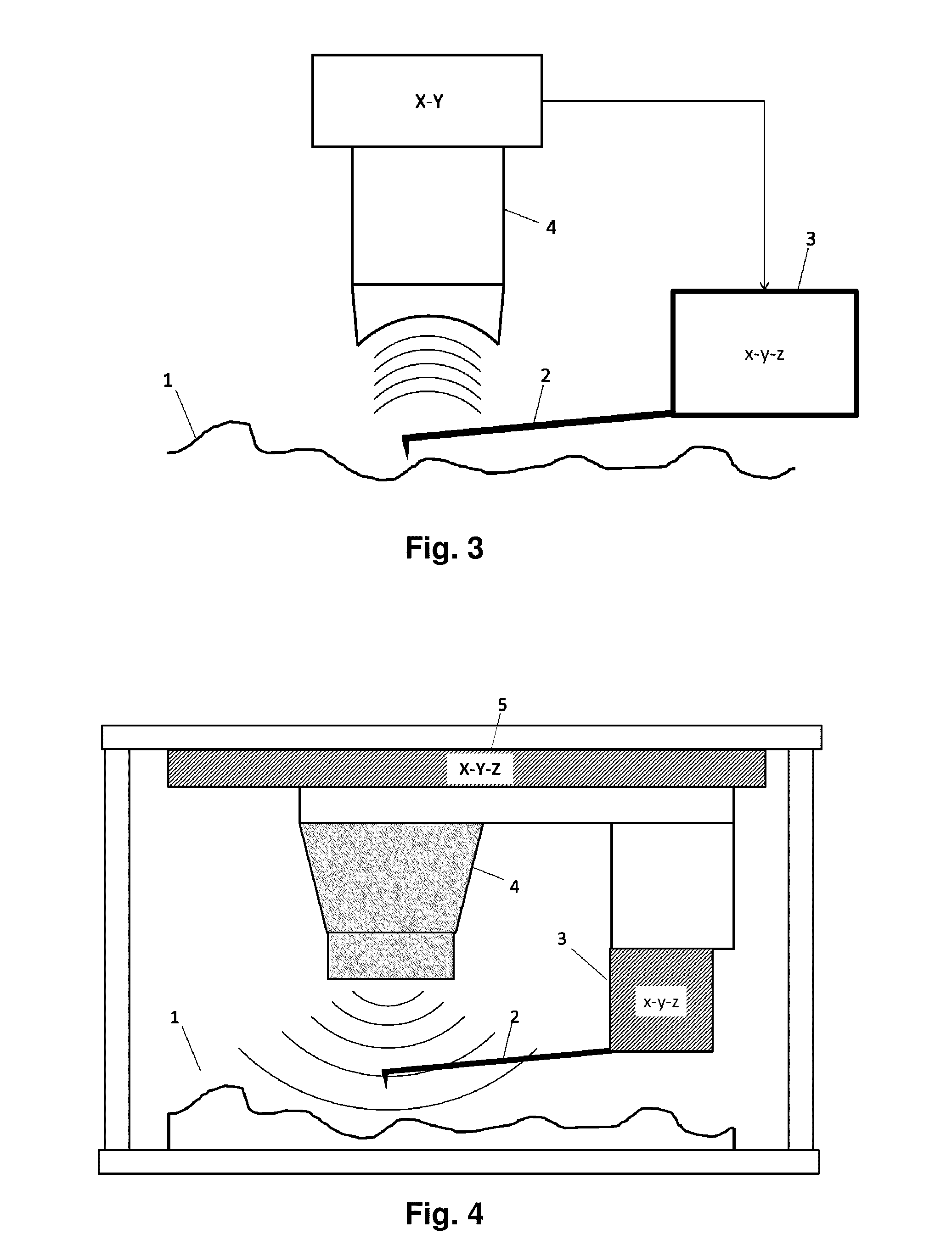
[0043]FIGS. 4 and 5 show a third embodiment where the overall map is obtained by an integrated PED-SPM, i.e. a combined mechanical and / or electronical device including the coarse approach system or PED 4 with its drive system 5 and the SPM 3. The PED here being used as part of the integral PED-SPM uses an optical mapping as described by, e.g., M. G. L. Gustafsson et al. in Biophys. Journal, 94, 4957-4970 (June 2008): “Three-dimensional resolution doubling in wide-field fluorescence microscopy by structured illumination”.

[0044]The method performed by the PED 4 is a three-dimensional scanning method using structured illumination of a sample. It has the advantage that large samples can be investigated rather quickly. Even samples that are larger than the optical field of view of the PED can be quickly scanned by relative movement between the sample and the PED. The details of this first step according to the invention are as follows.

[0045]The measurement is initiated by placing the sam...


PUM


Abstract

This invention concerns scanning probe microscopes and related instruments (“SPMs”) when used to investigate or measure large samples whose size is a multiple of the typical operational scanning area of an SPM, say 150 μm×150 μm at most. To avoid frequent readjustments or other time-consuming human interaction and errors when focusing the SPM, a multi-step, automated method for the SPM-scanning of large samples is disclosed, comprising a “coarse”, i.e. low resolution, non-SPM scanning or mapping step adapted to scan a large sample and providing an integral map of the sample, followed by a preferably mathematical evaluation step identifying areas of interest of the sample, which areas are then subjected to a focused “fine” raster scanning step by the SPM with high resolution. The associated apparatus provides the means to execute this novel three-step process.

Description

TECHNICAL FIELD OF THE INVENTION[0001]The present invention concerns scanning probe microscopes and other nanoscale cantilever-based or micromechanical instruments (here generally termed “SPMs”) and is directed to an improvement for investigating or measuring large areas or surfaces of two-dimensional or three-dimensional objects. Since the operational range of SPMs is very small, typically in the range of μm, the scanning of large areas is often a time-consuming task. Especially when scanning uneven, rough surfaces or large three-dimensional samples, frequent readjustments of the SPM are necessary which does not only require trained personnel for its execution, but also needs more time than may be available. Thinking e.g. of a medical or biological application, time can be of truly vital importance.[0002]The present invention provides a solution to this problem by a novel approach in form of a multi-step, automated method for the SPM-scanning of large samples. This novel approach l...

Claims


Application Information

Patent Timeline
IPC IPC(8): G01Q10/02G02B21/00G01B9/02
CPCG01Q10/02G02B21/0028G01B9/02091B82Y35/00G01Q30/02G01Q30/04H02S20/32Y02E10/50G06V20/693
Inventor SUM, ROBERTHOWALD, LUKAS EMANUELMATTER, URS
Owner NUOMEDIS
Why Eureka
Try Eureka