

Optical film with pressure sensitive adhesive on both sides and method for producing image display device using same
a technology of pressure sensitive adhesive and optical film, which is applied in the direction of film/foil adhesive, light source, polarising elements, etc., can solve the problems of deteriorating the visibility of the image display device, and achieve the suppression of bubble generation, the production process is simplified, and the effect of preventing the protrusion of liquid resin or pressure sensitive adhesive sheets
- Summary
- Abstract
- Description
- Claims
- Application Information
AI Technical Summary
Benefits of technology
Problems solved by technology
Method used
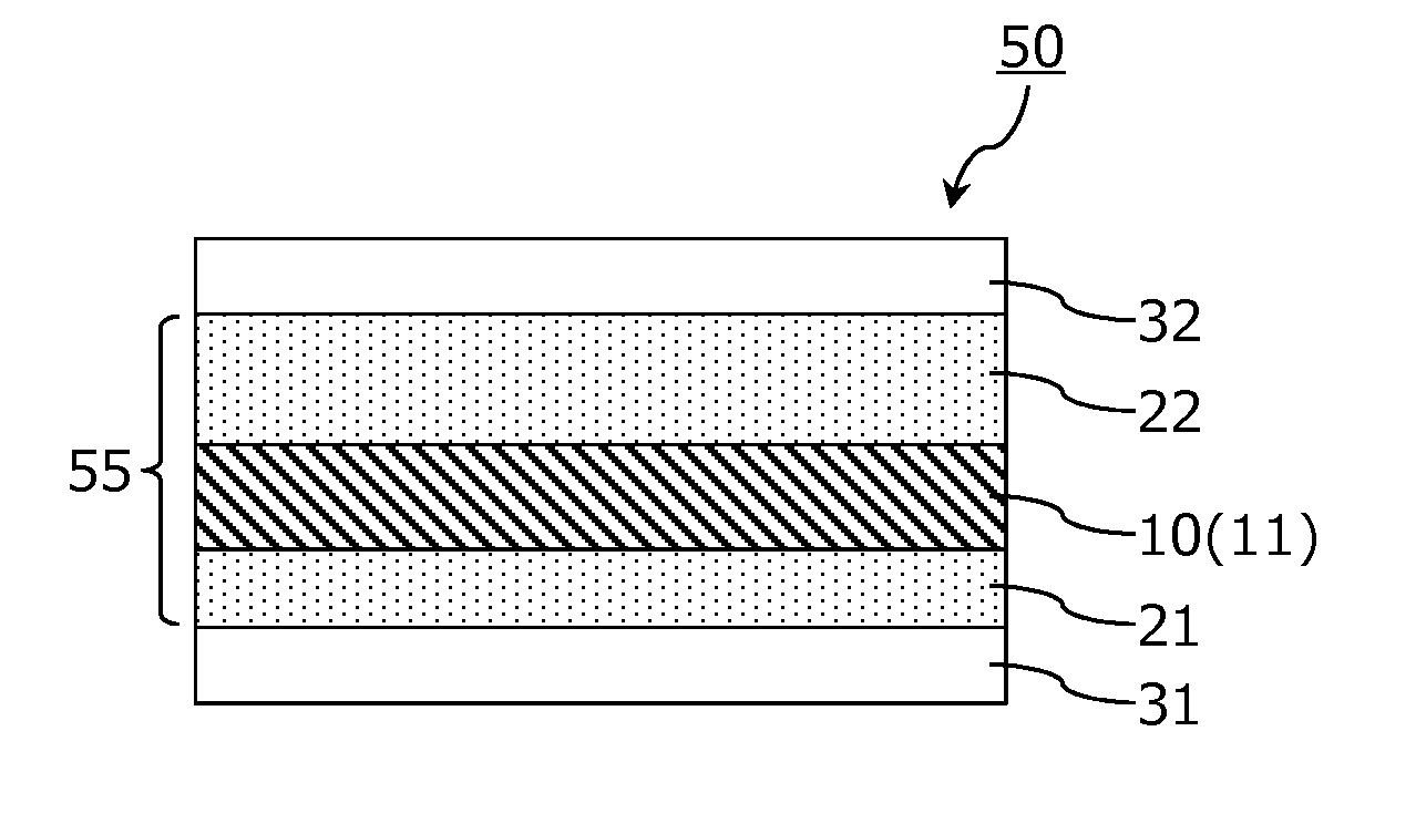
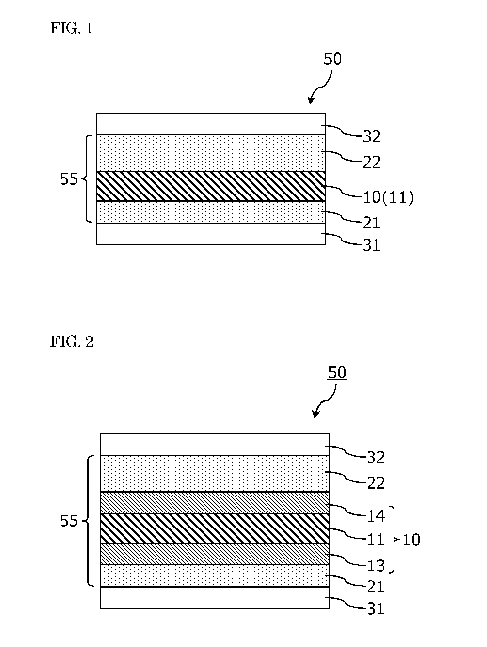
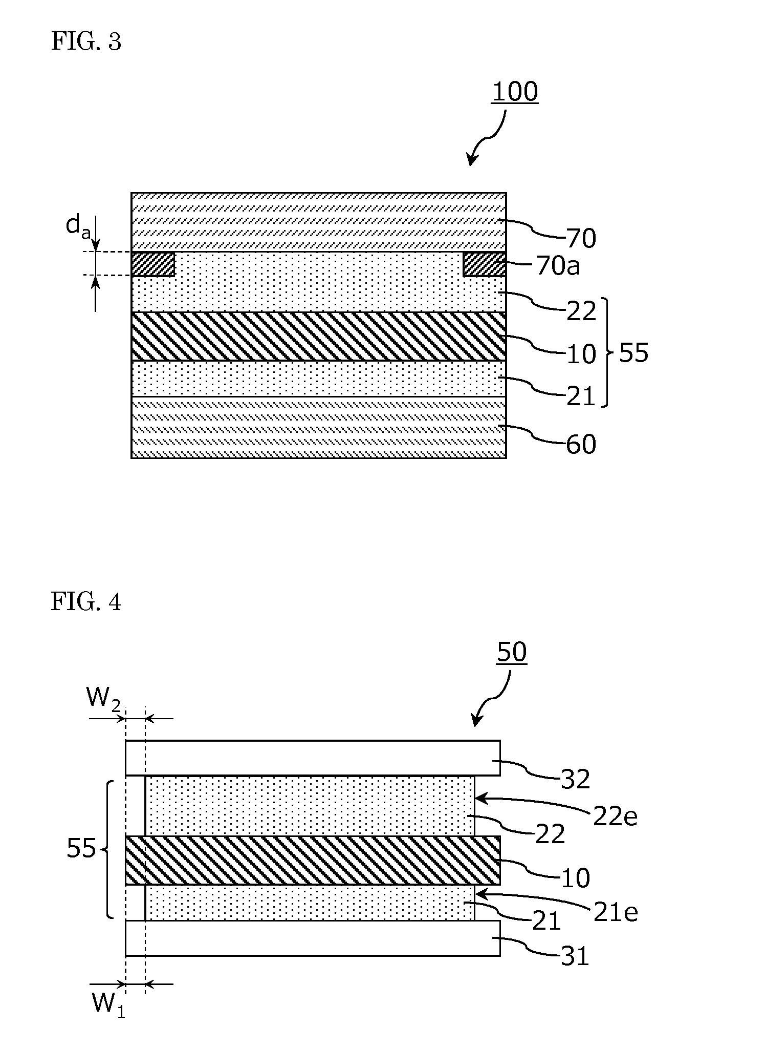
Image

Examples
example 1
Polarizing Plate
[0125]A polarizing plate (polarization degree: 99.995%) with a transparent protective film laminated on each of both surfaces of a polarizer formed of a 25 μm-thick stretched polyvinyl alcohol film impregnated with iodine was used. The transparent protective film on one surface (image display cell side) of the polarizer was a retardation film formed of a 40 μm-thick triacetyl cellulose film, and the transparent protective film on the other surface (viewing side) was a 60 μm-thick triacetyl cellulose film.
[0126]
[0127](Preparation of Base Polymer)
[0128]97 parts of butyl acrylate, 3 parts of acrylic acid, 0.2 parts of azobisisobutyronitrile as a polymerization initiator and 233 parts of ethyl acetate were introduced into a separable flask provided with a thermometer, a stirrer, a reflux cooling tube and a nitrogen gas inlet, and a nitrogen gas was then fed to perform nitrogen purge for 1 hour while the mixture was stirred. Thereafter, the flask was heated to 60° C., the...
examples 2 and 3
[0148]As the viewing side pressure sensitive adhesive layer B, a pressure sensitive adhesive composition (solution) having the composition shown in Table 1 was prepared. As a tackifier, a styrene oligomer (“YS Resin SX-85” manufactured by Yasuhara Chemical Co., LTD; softening point: 85° C.) was used in Example 2, and a nuclear hydrogenated terpene phenol (“YS Polyster NH” manufactured by Yasuhara Chemical Co., LTD; softening point: 130° C.) was used in Example 3. The pressure sensitive adhesive in each of Examples 2 and 3 is a photocurable pressure sensitive adhesive containing phenyl glycidyl ether acrylate (“New Frontier PGA” manufactured by Dai-ichi Kogyo Seiyaku Co., Ltd.) as a photocurable acryl-based monomer, and 1-hydroxycyclohexylphenylketone (“IRGACURE 184” manufactured by Ciba Specialty Chemicals Corporation) as a photoradical generator.
[0149]A polarizing plate with a pressure sensitive adhesive on both sides was prepared in the same manner as in Example 1 except that a ph...
examples 4 to 6
Preparation of Base Polymer
[0150]75 parts of 2-ethylhexyl acrylate (2EHA), 25 parts of hydroxyethyl acrylate HEA), 0.2 parts of azobisisobutyronitrile as a polymerization initiator and 233 parts of ethyl acetate were introduced into a separable flask provided with a thermometer, a stirrer, a reflux cooling tube and a nitrogen gas inlet, and a nitrogen gas was then fed to perform nitrogen purge for 1 hour while the mixture was stirred. Thereafter, the flask was heated to 70° C., the mixture was reacted for 5 hours to obtain an acryl-based polymer having a weight average molecular weight (Mw) of 700000 (hereinafter, this base polymer is referred to as a “polymer 2”).
[0151]
[0152]A pressure sensitive adhesive composition (solution) having the composition shown in Table 1 was prepared using the polymer 2. A polarizing plate with a pressure sensitive adhesive on both sides was prepared in the same manner as in Example 1 except that a pressure sensitive adhesive layer having the compositio...
PUM
| Property | Measurement | Unit |
|---|---|---|
| thickness | aaaaa | aaaaa |
| thickness | aaaaa | aaaaa |
| storage elastic modulus | aaaaa | aaaaa |
Abstract
Description
Claims
Application Information