Carbon nano-tube production from carbon dioxide

a carbon dioxide and carbon nanotube technology, applied in the direction of single-walled nanotubes, coatings, chemistry apparatus and processes, etc., can solve the problems of large amount of carbon dioxide, failure to efficiently decompose carbon dioxide, and high cost of methane as a direct source, and achieve the effect of high carbon dioxide conversion ra

Inactive Publication Date: 2016-01-28
SAUDI BASIC IND CORP SA
View PDF1 Cites 17 Cited by
  • Summary
  • Abstract
  • Description
  • Claims
  • Application Information

AI Technical Summary

Benefits of technology

[0008]The present invention provides a solution to the current problems facing the production of carbon nanotubes. The solution is premised on the use of a new chemical vapor deposition integrated process (referenced throughout as “CVD-IP”) that utilizes two reaction chambers which are connected to one another (e.g., in flow connection from the first chamber to the second chamber; a valve could be used to separate the two chambers). In the first reaction chamber the carbon dioxide can be converted into methane. In the second reaction chamber carbon nanotubes can be produced from the formed methane using a chemical vapor deposition process. As illustrated in the Examples, this process can result in a high carbon dioxide conversion rate (e.g., upwards of nearly 100%) and a carbon-based yield of carbon nanotubes that is at least 20, 25, 30, 35, or 40% or more, neither of which has been achieved in current carbon nanotube processes that utilize carbon dioxide as the direct carbon source. Even more, these results can be achieved with a single pass-through or run through of the process. Multiple runs utilizing the original starting carbon source (e.g., carbon dioxide) do not have to be performed to achieve these conversion and yield rates.

Problems solved by technology

One of the problems, however, has been to identify an efficient process by which to produce carbon nanotubes.
Unfortunately, methane as a direct source can be relatively expensive.
Such a process, however, oftentimes fails to efficiently decompose the carbon dioxide, which leaves a substantial amount of carbon dioxide as a by-product.
This can be undesirable given the potential links between carbon dioxide emissions and global warming and may further require a second pass through or sequestration of the carbon dioxide, both of which add to the complexity of the process.
Such processes, however, oftentimes fail to efficiently utilize the carbon dioxide and can lead to problems such as those discussed above.

Method used


Image

  • Carbon nano-tube production from carbon dioxide
  • Carbon nano-tube production from carbon dioxide
  • Carbon nano-tube production from carbon dioxide

Examples


example 1

Carbon Dioxide Conversion and Carbon Nanotube Production

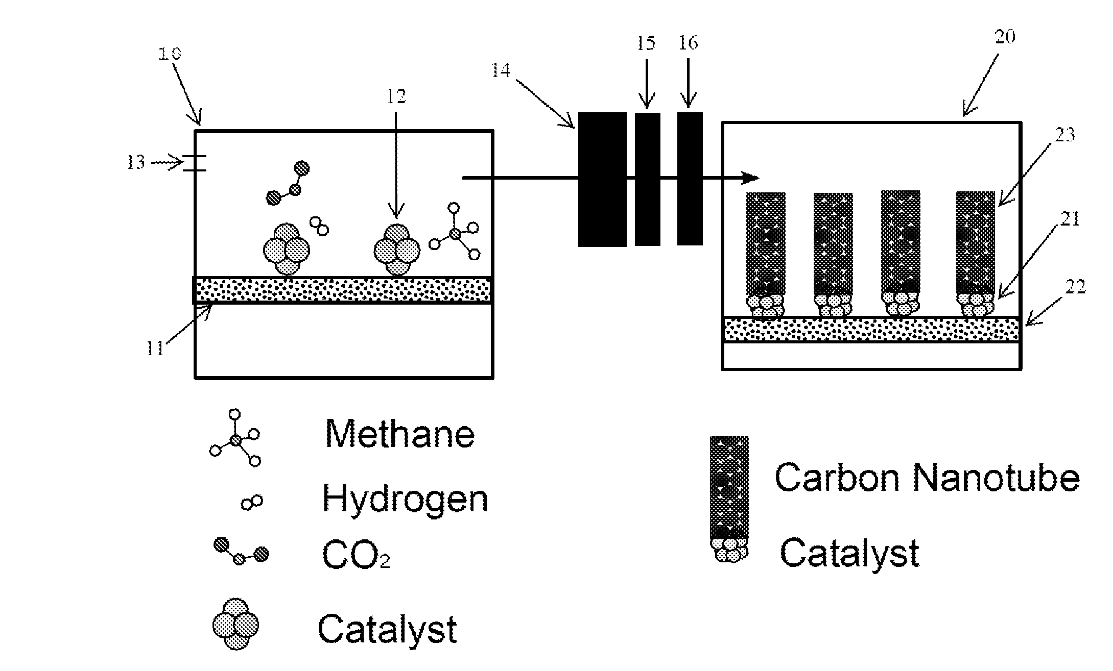
[0036]Example 1 references FIG. 1 for illustrative purposes. A nickel-based catalyst 12 was synthesized by a citric acid combustion method to produce powders (see Ran M F, Liu Y, Chu W, Liu Z B, Borgna A. Catal Commun, 2012, 27: 69; Ran M F, Sun W J, Liu Y, Chu W, Jiang C F. J Solid State Chem, 2013, 197: 517; Wen J, Chu W, Jiang C F, Tong D G. J Nat Gas Chem, 2010, 19(2): 156, both of which are incorporated by reference). 500 milligrams (mg) of the catalyst 12 was placed in a ceramic boat 11. The ceramic boat 11 was placed into a quartz reactor 10. The catalyst 12 was reduced in the presence of pure hydrogen at a temperature of 550° C. for a period of 120 minutes. Pure carbon dioxide was fed into the quartz reactor 10 at a flow rate of 15 ml / min or 30 ml / min and hydrogenated to methane and water at a temperature of 300-380° C. for a period of 120 minutes to 360 minutes. The inlet hydrogen flowrate was at about the stoichiometr...

example 2

Characterization of the CO2 Derived CNT Samples and Results

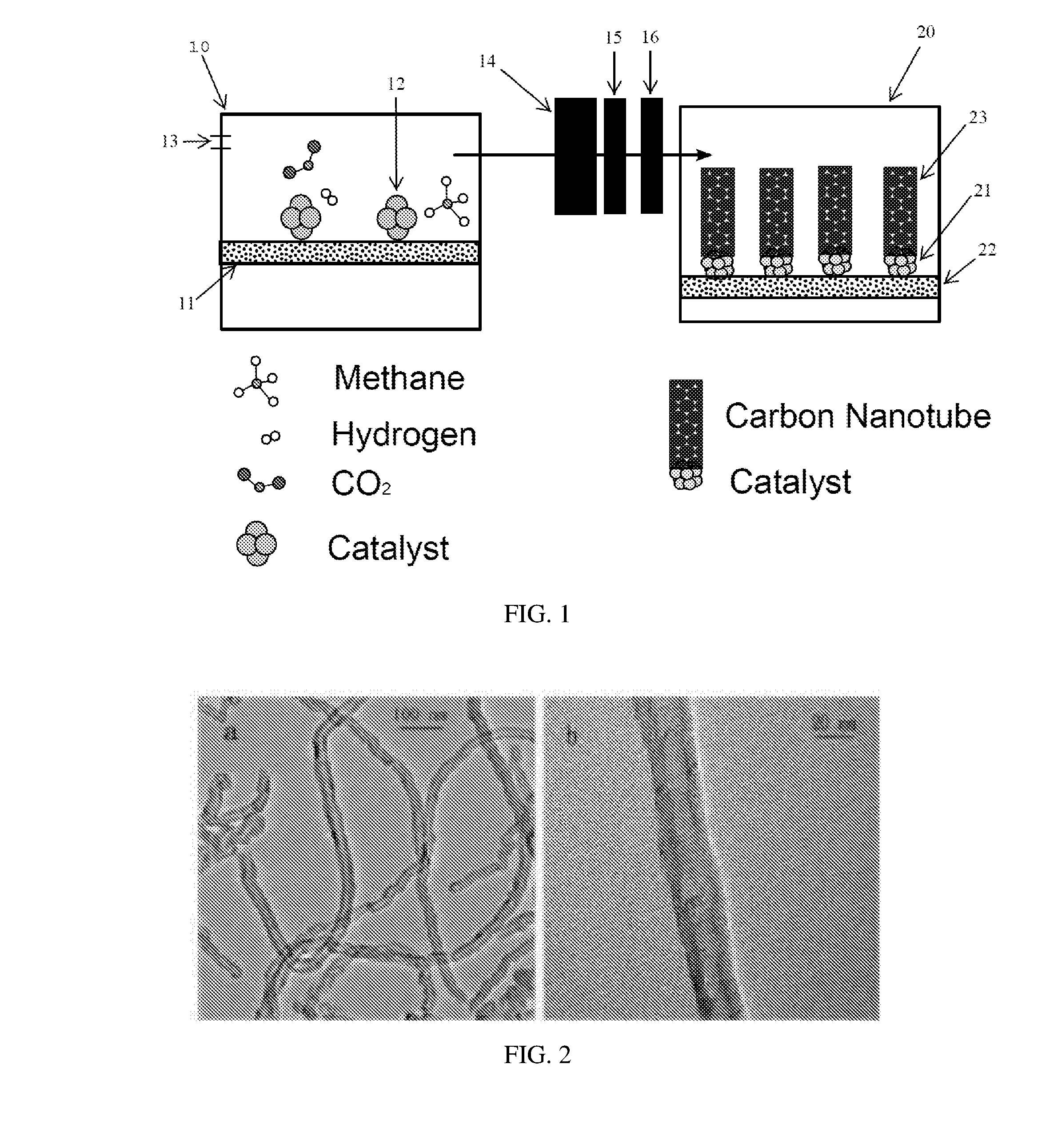
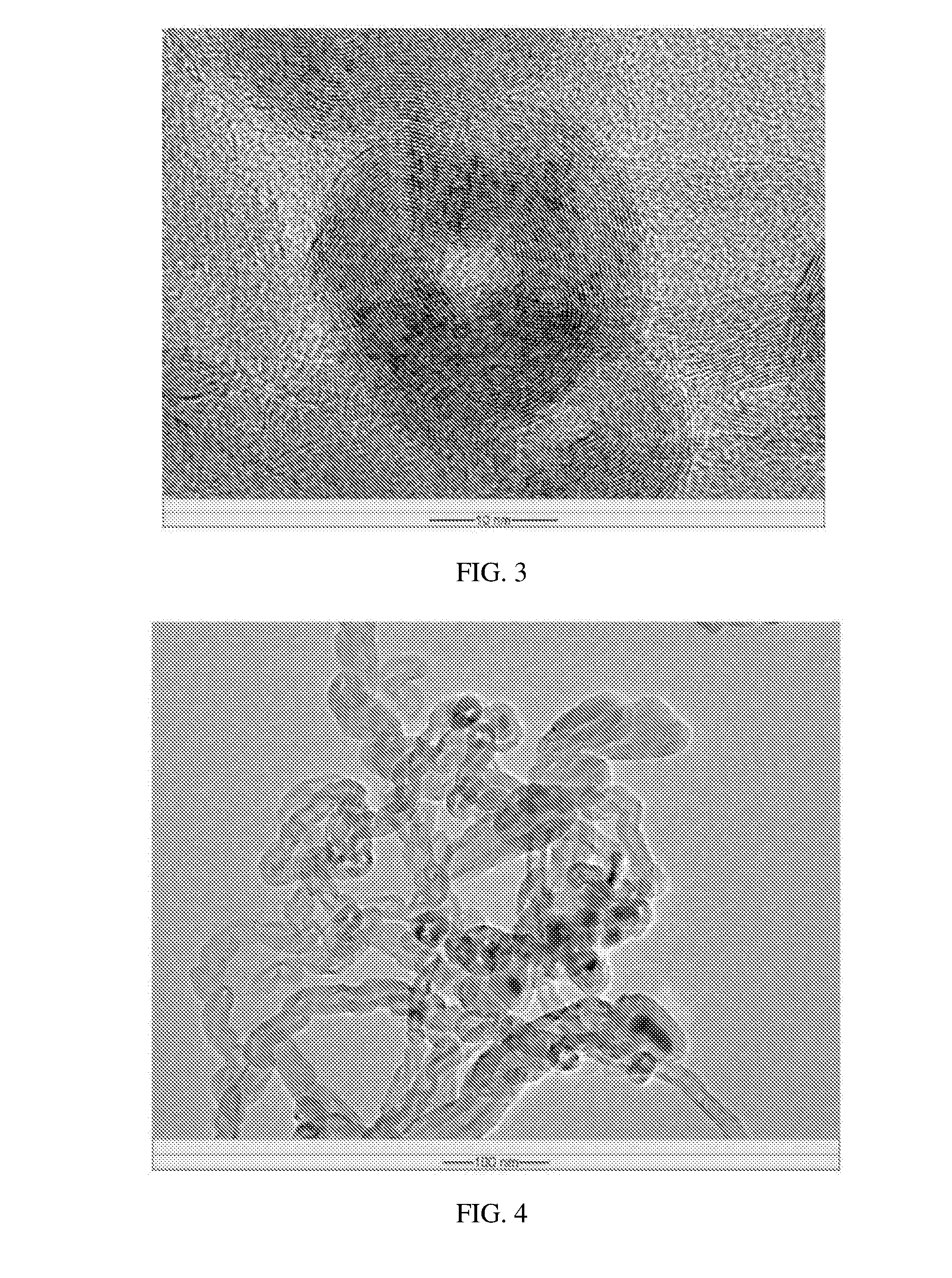
[0041]The samples in Table 1 were characterized by several techniques using XRD, TEM, FT-IR, TG-DTG, etc. (see A. Y. Khodakov, W. Chu and P. Fongarland, Chem Rev, 2007, 107, 1692; W. Chu, P. A. Chernayskii, L. Gengembre, G. A. Pankina, P. Fongarland and A. Y. Khodakov, J Catal, 2007, 252, 215, both of which are incorporated by reference). The X-ray diffraction patterns were measured and collected on an XRD Bruker D8 diffractometer with Cu Ka radiation. Transmission electron microscopy (TEM) images were obtained from a JEOL JEM-2000 FX microscope at 200 kV in National University of Singapore (NUS). The samples were prepared by ultrasonic dispersion in an ethanol solution, placed on a copper TEM grid, and evaporated. Scanning electron microscope (SEM) images were obtained on a Philips FEG XL-30 system. Room temperature micro-Raman scattering analyses were carried out with a Renishaw spectrometer using Ar laser excitation sourc...

example 3

Nickel Catalyst System (Ni-A303) for the CVD-IP Process of MWCNTs Production from Carbon Dioxide and Effects of Reaction Temperature for CVD Process

[0051]For the preparation of another nickel containing catalyst, Ni-A303, the sample precursor was dried at 110° C. for 12 hours (h), and then calcined at 700° C. for 6 h. The second reaction (CVD process) was operated at a temperature in the range of 600° C. to 800° C. (Expt. 15-19).

[0052]To grow nanotubes, the two-step integrated CVD-IP new process has been utilized. Typically, 150 mg CVD catalyst (Ni-A303) in a ceramic boat was placed in the quartz reactor 2, followed by a reduction in pure H2 at 550 C for 60 minutes. Then the CO2 / H2 mixed gas was feed in the integrated process system. The carbon nanotube (MWCNTs) production was performed at different reaction temperature (at one temperature in the range of 600° C. to 800° C.). The inlet carbon dioxide was fixed at a flow rate of 30 ml / min, the MWCNTs growth process lasted for 120 min...


PUM

PropertyMeasurementUnit
temperatureaaaaaaaaaa
flow rateaaaaaaaaaa

Abstract

Disclosed is a method for making carbon nanotubes comprising (a) reducing a nickel containing catalyst with a reducing agent in a first reaction chamber, (b) contacting the nickel containing catalyst with carbon dioxide under conditions sufficient to produce a reaction product, (c) transferring the reaction product to a second reaction chamber, wherein the second reaction chamber comprises a Group VIII metal containing catalyst, and (d) contacting the Group VIII metal containing catalyst with the reaction product under conditions sufficient to produce carbon nanotubes, wherein the first and second reaction chambers are in flow connection during the transfer step (c), wherein the only source of carbon used to form the carbon nanotubes is from the carbon dioxide used in step (b), and wherein at least 20% of the carbon from the carbon dioxide used in step (b) is converted into carbon nanotubes.

Description

BACKGROUND OF THE INVENTION[0001]A. Field of the Invention[0002]The present invention relates to methods for producing carbon nanotubes from carbon dioxide.[0003]B. Description of Related Art[0004]Carbon nanotubes have previously been characterized as allotropes of carbon with a cylindrical nanostructure. These structures are valuable for nanotechnology, electronics, optics and other fields of materials science and technology. For instance, carbon nanotubes have been incorporated into a variety of products (e.g., nanotube-based transistors, circuits, cables, wires, batteries, solar cells, baseball bats, golf clubs, car parts etc.).[0005]One of the problems, however, has been to identify an efficient process by which to produce carbon nanotubes. For instance, several processes utilize methane as the direct carbon source. Unfortunately, methane as a direct source can be relatively expensive.[0006]Another reported process is to decompose carbon dioxide into carbon monoxide followed by ...

Claims


Application Information

Patent Timeline
Patent Type & Authority Applications(United States)
IPC IPC(8): C01B31/02C01B31/00C23C16/26C23C16/448
CPCC01B31/0233C01B31/00C23C16/4488C01B2202/36C01B2202/06C01B2202/02C23C16/26C01B32/00C01B32/16C01B32/162
Inventor WEI, CHU
Owner SAUDI BASIC IND CORP SA
Why Eureka
Try Eureka