

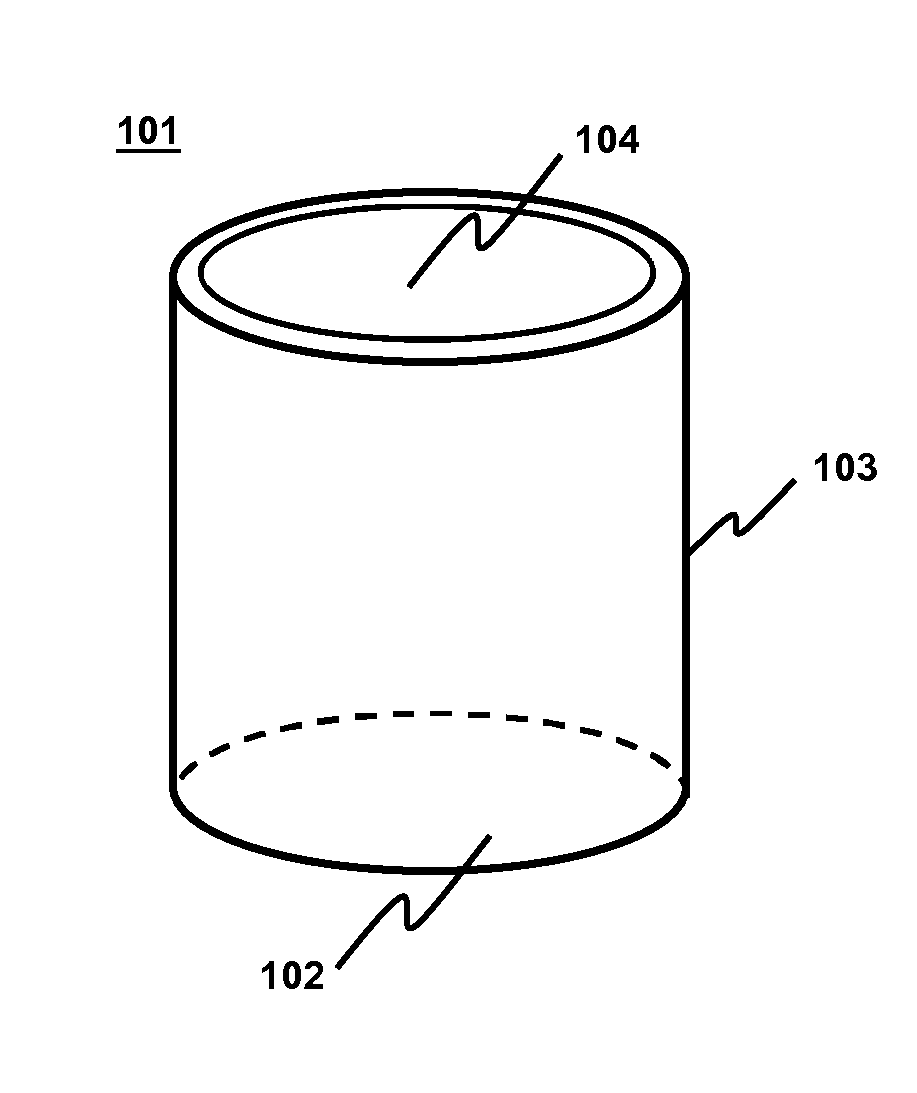
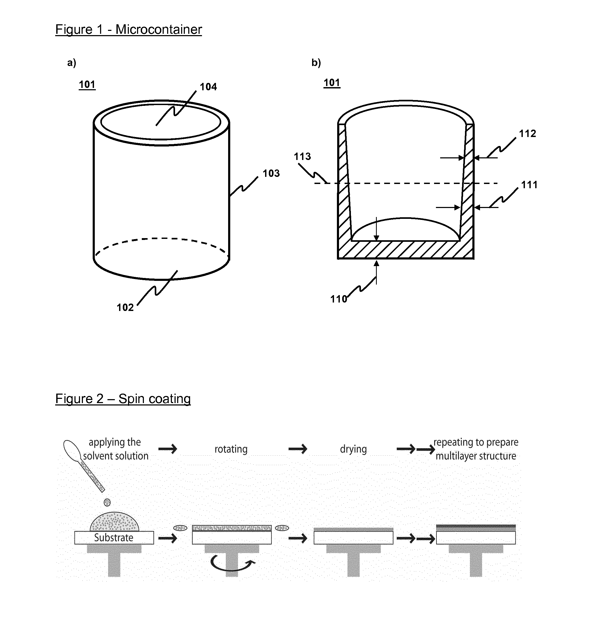
Method for the fabrication of multi-layered micro-containers for drug delivery
a technology of multi-layered micro-containers and drug delivery, which is applied in the direction of containers, tray containers, domestic articles, etc., can solve the problems of complex multi-step process, low bioavailability, and several obstacles in the pharmaceutical industry
- Summary
- Abstract
- Description
- Claims
- Application Information
AI Technical Summary
Benefits of technology
Problems solved by technology
Method used
Image

Examples
example 1
Spin Coating of Polycaprolactone / Furosemide on Silicon Wafer (Core Layer)
[0226]A polymer-drug core layer was fabricated by spin coating of a solution of polycaprolactone (PCL) and the diuretic drug furosemide on a standard 4-inch single crystal (SC) silicon wafer supplied by Okmetic (Vantaa, Finland). All the chemicals were obtained from Sigma-Aldrich and were used as recieved. A solution consisting of 20 mL dichloromethane, 40 mL acetone, 8 g PCL and 2 g furosemide was prepared and kept on a hotplate at a temperature of 50° C. for at least 48 h. During heating constant magnetic stirring was applied to achieve a homogeneous polymer solution. The solution was cooled to room temperature (RT) before spin coating. The spin coating was performed on an RC8 spin coater (Karl Suss, Lyon, France). The polymer-drug solution was dispensed on a silicon wafer rotating at 200 rpm. The wafer is then accelerated with 2000 rpm / s to the final spin speed of 1000 rpm which was maintained for 60 s. The ...
example 2
Spin Coating of PCL on PCL / Furosemide Layer (Barrier Layer)
[0227]A polymer barrier layer was deposited onto the polymer-drug core layer by spin coating of a solution of PCL. The polymer solution consisted of 8 g PCL in 40 mL dichloromethane. The preparation of the polymer solution and the spin coating followed an identical procedure as described in example 1 for the polycaprolactone / furosemide layer. The resulting thickness of the barrier layer was 10 μm.
example 3
Fabrication of Embossing Stamp
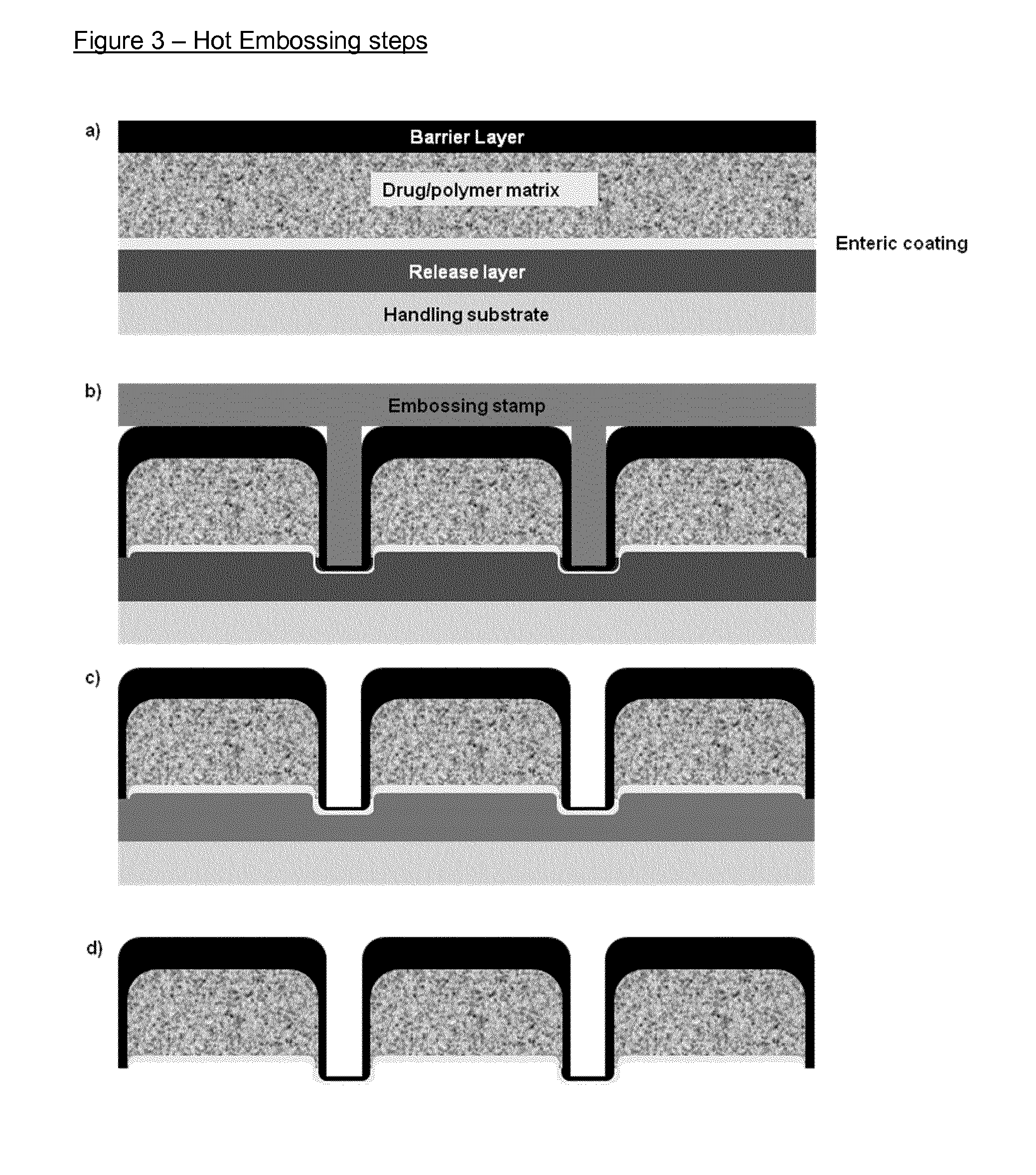
[0228]For hot embossing, a stamp with vertical or near vertical sidewalls may be preferable. Negative slopes are typically avoided because of the risk of trapping the polymer in the stamp, and also because it hinders the removal of the stamp after completed processing. For the embossing of the micropatches a fabrication process for nickel stamps with positive sidewall slopes is developed. This should support the enclosure of the core layer by the barrier layer during the embossing process.
[0229]The stamp fabrication is based on electroplating of nickel on a silicon template followed by removal of the template. First, 500 nm of wet silicon oxide were deposited on a standard 4-inch SC silicon wafer during 50 min in a LPCVD furnace (Tempress, MD Vaassen, the Netherlands) at 1100° C. Next, the wafer was coated with hexamethyldisiloxane (HMDS) and a 1.5 μm thick film of positive photoresist AZ5214e (Clariant GmbH, Wiesbaden, Germany) was applied by spin coat...
PUM
| Property | Measurement | Unit |
|---|---|---|
| Temperature | aaaaa | aaaaa |
| Temperature | aaaaa | aaaaa |
| Temperature | aaaaa | aaaaa |
Abstract
Description
Claims
Application Information