Boiler system and power plant including the same
a boiler system and power plant technology, applied in the direction of machines/engines, mechanical equipment, lighting and heating apparatus, etc., can solve the problems of large amount of sulfur oxide mixed, increased pressure loss, and sulfur oxide contained in the combustion gas reacting with metal to corrode metal, so as to achieve the effect of not reducing the thermal efficiency of the entire boiler system
- Summary
- Abstract
- Description
- Claims
- Application Information
AI Technical Summary
Benefits of technology
Problems solved by technology
Method used
Image
Examples
first embodiment
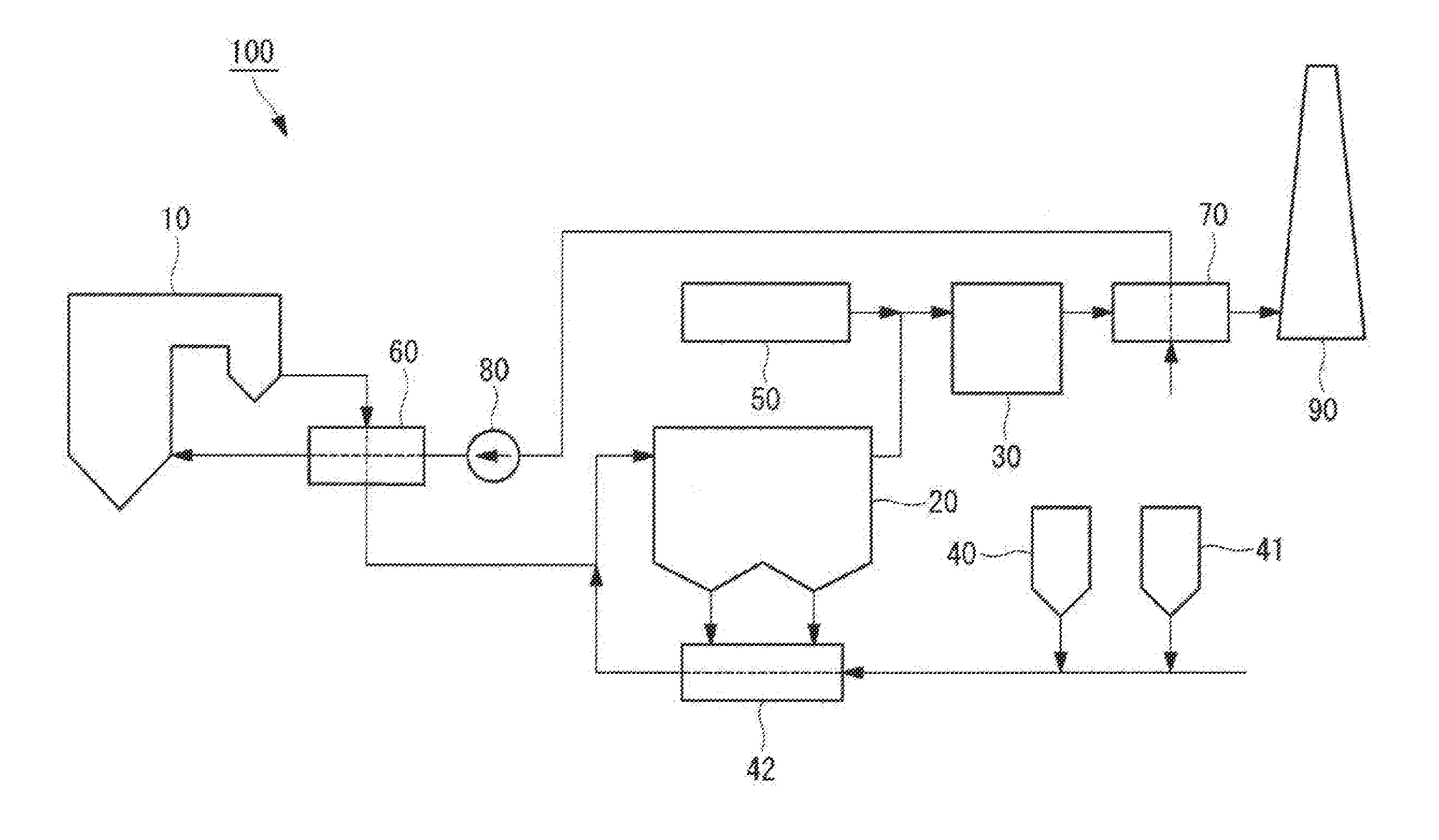
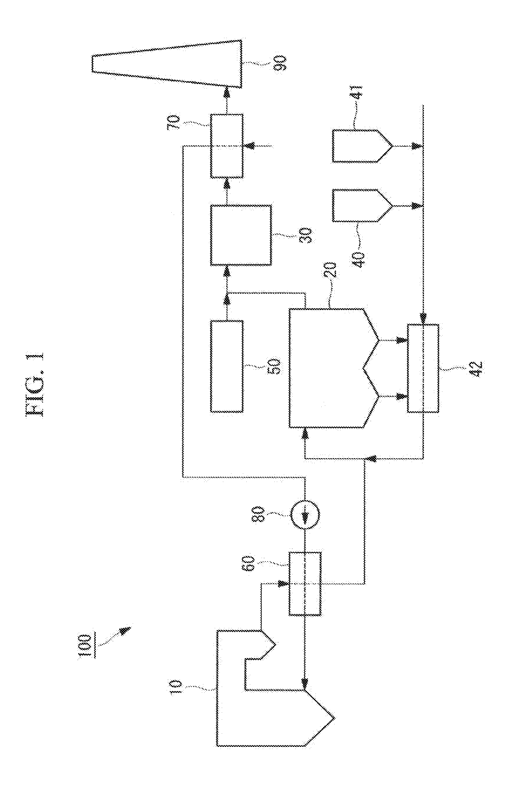
[0069]With reference to the drawings, a boiler system 100 according to a first embodiment of the present invention will be described.
[0070]The boiler system 100 of this embodiment is a coal-fired boiler system that uses, as fuel, pulverized coal obtained by pulverizing coal fuel to desired fineness using a coal pulverizer (not shown). The boiler system 100 is included in a power plant (not shown). The boiler system 100 generates high temperature steam from heat generated by burning pulverized coal, and supplies the steam to a steam turbine (not shown) connected to a generator (not shown). Power of the steam turbine rotated by the steam is transferred to the generator to generate electricity. As such, the boiler system 100 of this embodiment constitutes a part of the power plant (not shown).
[0071]As shown in FIG. 1, the boiler system 100 of this embodiment includes a boiler 10, a fabric filter 20 (removal section), a denitration section 30, a desulfurizing absorbent supply section 40...
second embodiment
[0145]Next, with reference to the drawings, a boiler system 200 according to a second embodiment of the present invention will be described.
[0146]The second embodiment is a modification of the first embodiment, and is the same as the first embodiment except as particularly described below, and thus descriptions will be omitted.
[0147]In the boiler system 100 of the first embodiment, the fabric filter 20 removes sulfur oxide contained in the combustion gas, and the denitration section 30 removes nitrogen oxide contained in the combustion gas. In this embodiment, a fabric filter 20′ supports a denitrating catalyst and thus removes both sulfur oxide and nitrogen oxide.
[0148]As shown in FIG. 5, the boiler system 200 of this embodiment does not include the denitration section 30 included in the boiler system 100 of the first embodiment. In the boiler system 200 of this embodiment, a reformer 50 mixes a gas mainly containing carbon monoxide (CO) and hydrogen (H2) as reagents into the combu...
third embodiment
[0157]Next, a boiler system according to a third embodiment of the present invention will be described.
[0158]The third embodiment is a modification of the first or second embodiment, and is the same as the embodiments except as particularly described below, and thus descriptions will be omitted.
[0159]The boiler system of this embodiment is such that an oxidation treatment section (not shown) is added to the boiler system 100 of the first embodiment or the boiler system 200 of the second embodiment.
[0160]The oxidation treatment section is provided in a flow path of a combustion gas between a boiler 10 and an air preheater 60.
[0161]The oxidation treatment section is a device for oxidizing sulfur dioxide (SO2) as sulfur oxide contained in the combustion gas exhausted from the boiler 10 into sulfur trioxide (SO3). The oxidation treatment section uses vanadium pentoxide (V2O5) as a catalyst, and causes a reaction between oxygen in air and sulfur dioxide to generate sulfur trioxide.
[0162]...
PUM
 Abstract
Description
Claims
Application Information
 - R&D
- Intellectual Property
- Life Sciences
- Materials
- Tech Scout
- Unparalleled Data Quality
- Higher Quality Content
- 60% Fewer Hallucinations
Browse by: Latest US Patents, China's latest patents, Technical Efficacy Thesaurus, Application Domain, Technology Topic, Popular Technical Reports.
© 2025 PatSnap. All rights reserved.Legal|Privacy policy|Modern Slavery Act Transparency Statement|Sitemap|About US| Contact US: help@patsnap.com


