High-performance NdFeB permanent magnet comprising nitride phase and production method thereof

a technology of nitride phase and ndfeb permanent magnet, which is applied in the field of high-performance ndfeb permanent magnet comprising nitride phase and the production method thereof, can solve the problems of reducing the consumption of dy, and saving raw material costs. , to achieve the effect of reducing the generation of r—n compounds, reducing the performance of ndfeb permanent magn

Active Publication Date: 2017-04-06
SHENYANG GENERAL MAGNETIC
View PDF5 Cites 7 Cited by
  • Summary
  • Abstract
  • Description
  • Claims
  • Application Information

AI Technical Summary

Benefits of technology

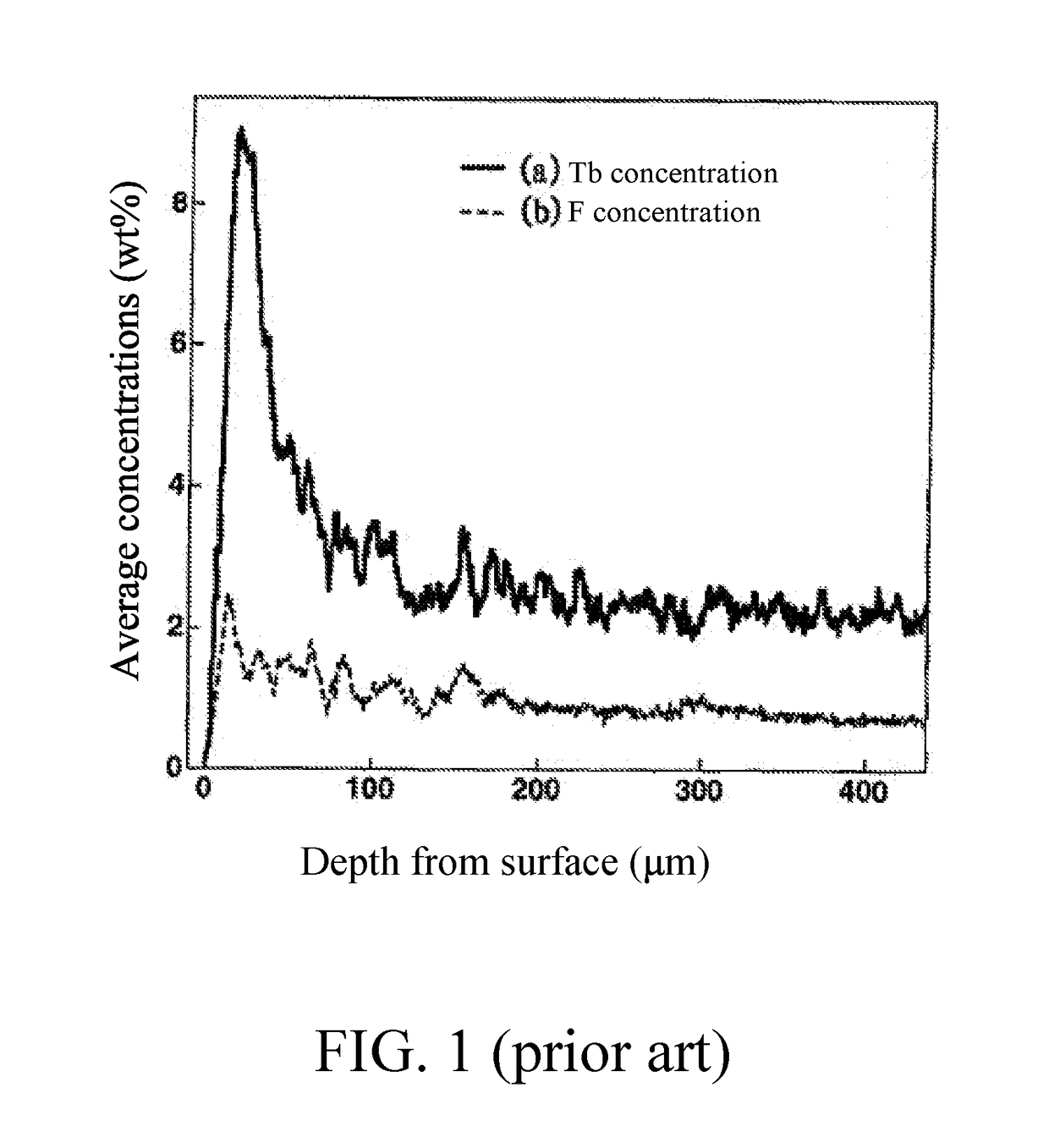
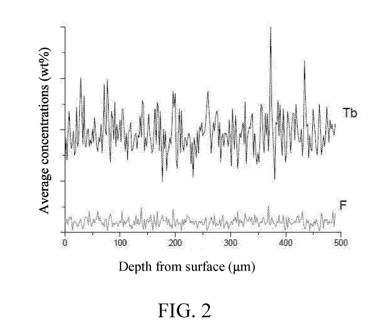
[0010]According to the prior art, N is regarded as a harmful element in a NdFeB rare earth permanent magnet, which decreases a performance of the NdFeB permanent magnet. It is found by the present invention that: when melting and sintering, an increase of N really decreases a magnetic performance; however, through improving a producing process, increasing an N content during preparing powders through a jet mill, especially increasing an N content of ultrafine powders, controlling sintering process parameters during sintering, removing part of needless N, decreasing a generation of R—N compounds, and allowing N to enter a main phase, the magnetic performance is obviously increased. Moreover, the present invention partially replaces B by N, which increases the magnetic performance of the NdFeB rare earth permanent magnet, especially a coercive force of the NdFeB rare earth permanent magnet.

Problems solved by technology

According to the prior art, N is regarded as a harmful element in a NdFeB rare earth permanent magnet, which decreases a performance of the NdFeB permanent magnet.
An entrance of N into the main phase obviously increases a service temperature of NdFeB, reduces a consumption of Dy, and saves a raw material cost.

Method used


Image

  • High-performance NdFeB permanent magnet comprising nitride phase and production method thereof
  • High-performance NdFeB permanent magnet comprising nitride phase and production method thereof

Examples


example 1

[0055]According to weight percent, preparing raw materials of praseodymium-neodymium alloys, metallic terbium, dysprosium fluorides, dysprosium-ferrum, pure iron, ferro-boron, metallic gallium, metallic zirconium, metallic cobalt, metallic aluminum and metallic copper into an alloy raw material having a composition of Pr6.3Nd23.1Dy2Tb0.6B0.95Co1.2Zr0.12Ga0.1Al0.2Cu0.2Ferest; loading the pure iron, the ferro-boron, the dysprosium fluorides, and a small amount of the praseodymium-neodymium alloys into a first charging basket; loading a rest of praseodymium-neodymium alloys, the dysprosium-ferrum, the metallic terbium, and the metallic gallium into a second charging basket; loading the metallic zirconium, the metallic cobalt, the metallic aluminum and the metallic copper into a third charging basket; sending the three charging baskets into a vacuum loading chamber of a vacuum melting rapid-solidifying device; after evacuating, opening the vacuum loading chamber and a vacuum valve of a ...

contrast example 1

[0058]According to weight percent, preparing raw materials of praseodymium-neodymium alloys, metallic terbium, dysprosium-ferrum, pure iron, ferro-boron, metallic gallium, metallic zirconium, metallic cobalt, metallic aluminum and metallic copper into an alloy raw material having a composition of Pr6.3Nd23.1Dy2Tb0.6B0.05Co1.2Zr0.12Ga0.1Al0.2Cu0.2Ferest; loading the pure iron, the ferro-boron, and a small amount of the praseodymium-neodymium alloys into a first charging basket; loading a rest of praseodymium-neodymium alloys, the dysprosium-ferrum, the metallic terbium, and the metallic gallium into a second charging basket; loading the metallic zirconium, the metallic cobalt, the metallic aluminum and the metallic copper into a third charging basket; melting the raw materials in the three charging baskets with the same steps in the example 1, and forming third alloy flakes having a same composition as the first alloy flakes in the example 1; sending the third alloy flakes and second...

contrast example 2

[0060]According to weight percent, preparing raw materials of praseodymium-neodymium alloys, metallic terbium, dysprosium-ferrum, pure iron, ferro-boron, metallic gallium, metallic zirconium, metallic cobalt, metallic aluminum and metallic copper into an alloy raw material having a composition of Pr6.3Nd23.1Dy2Tb0.6B0.95Co1.2Zr0.12Ga0.1Al0.2Cu0.2Ferest; loading the pure iron, the ferro-boron, and a small amount of the praseodymium-neodymium alloys into a first charging basket; loading a rest of praseodymium-neodymium alloys, the dysprosium-ferrum, the metallic terbium, and the metallic gallium into a second charging basket; loading the metallic zirconium, the metallic cobalt, the metallic aluminum and the metallic copper into a third charging basket; melting the raw materials in the three charging baskets with the same steps in the example 1, and forming third alloy flakes having a same composition as the first alloy flakes in the example 1; sending the third alloy flakes and second...


PUM

PropertyMeasurementUnit
temperatureaaaaaaaaaa

Abstract

A high-performance NdFeB permanent magnet including a nitride phase and a production method thereof are provided. A main phase of the NdFeB permanent magnet has a structure of R2T14B; a grain boundary phase is distributed around the main phase and contains N, F, Zr, Ga and Cu; a composite phase containing R1, Tb and N exists between the main phase and the grain boundary phase and includes a phase having a structure of (R1, Tb)2T14(B, N). R represents at least two rare earth elements, and includes Pr and Nd; T represents Fe, Mn, Al and Co; R1 represents at least one rare earth element, and includes at least one of Dy and Tb; the main phase contains Pr, Nd, Fe, Mn, Al, Co and B; and the grain boundary phase further contains at least one of Nb and Ti. Through placing partially B by N, a magnetic performance is increased.

Description

CROSS REFERENCE OF RELATED APPLICATION[0001]The application claims priority under 35 U.S.C. 119(a-d) to CN 201610215687.X, filed Apr. 8, 2016.BACKGROUND OF THE PRESENT INVENTION[0002]Field of Invention[0003]The present invention relates to a rare earth permanent magnet field, and more particularly to a high-performance NdFeB permanent magnet comprising a nitride phase and a production method thereof.[0004]Description of Related Arts[0005]The NdFeB rare earth permanent magnet is the widely applied basic electronic component and electrical apparatus element in the world, and is widely applied in computer, mobile phone, television, automobile, electrical machine, toy, sound system, automatic equipment, and magnetic resonance imaging. With the energy-saving and low-carbon economy requirements, the NdFeB rare earth permanent magnet is further applied in fields of energy-saving household appliance, hybrid electric vehicle, and wind power generation.[0006]In 1983, the sintered NdFeB rare e...

Claims


Application Information

Patent Timeline
Patent Type & Authority Applications(United States)
IPC IPC(8): H01F1/057C22C38/16C22C38/14C22C38/10C22C38/06C22C38/00C22C33/04B22F9/08B22F1/00B22F9/04B22F3/16B22F3/087B22F3/10C21D9/00C21D6/00H01F41/02B22F1/068
CPCH01F1/057B22F2201/20C22C38/16C22C38/14C22C38/10C22C38/06C22C38/005C22C38/002C22C33/04B22F9/08B22F1/0055B22F9/04B22F3/16B22F3/087B22F3/1017C21D9/00C21D6/007B22F2009/044B22F2201/02H01F41/0266H01F1/0571H01F1/0575H01F41/026B22F1/068H01F1/0577H01F1/059H01F41/0293B22F3/101B22F3/162C22C33/02B22F2998/10B22F2999/00C22C2202/02B22F2009/048B22F3/02B22F3/10B22F2201/05
Inventor SUN, BAOYUDUAN, YONGLI
Owner SHENYANG GENERAL MAGNETIC
Why Eureka
Try Eureka