Thermoelectric Conversion Element and Thermoelectric Conversion Module

a technology of thermoelectric conversion module and conversion element, which is applied in the direction of generator/motor, manufacturing tools, and so on, can solve the problems of oxidation, melting, and lagging in the development of thermoelectric conversion elements and thermoelectric generation modules, and achieve excellent thermoelectric conversion performance, excellent bonding strength, and excellent performan

Inactive Publication Date: 2017-05-04
NAT INST OF ADVANCED IND SCI & TECH
View PDF4 Cites 5 Cited by
  • Summary
  • Abstract
  • Description
  • Claims
  • Application Information

AI Technical Summary

Benefits of technology

[0133]The thermoelectric conversion elements and thermoelectric conversion module of the present invention use specific silicides that show excellent performance in an intermediate temperature range of room temperature to about 700° C., as thermoelectric conversion materials. As a bonding agent for bonding these thermoelectric conversion materials to conductive substrates, a paste containing, as conductive metals, silver and at least one noble metal selected from the group consisting of gold, platinum, and palladium is used. In this manner, appropriate conductivity is imparted to the joints of the thermoelectric conversion materials. Further, even when electric generation is repeated in an intermediate temperature range, excellent bonding strength is maintained, and the silver contained in the conductive paste does not diffuse into the thermoelectric conversion materials, maintaining excellent thermoelectric conversion performance for a long period of time.
[0134]The use of the thermoelectric conversion module of the present invention enables effective use of a heat source in an intermediate temperature range of room temperature to about 700° C., making efficient thermoelectric generation possible over a long period of time.

Problems solved by technology

In this manner, humankind wastes a vast amount of heat energy, and obtains only a small amount of energy from activities such as combustion of fossil energy.
However, the development of thermoelectric conversion elements and thermoelectric generation modules is currently lagging behind, compared to the development of thermoelectric conversion materials themselves.
However, thermoelectric generation performed using waste heat having a temperature as high as 400° C. or higher would cause oxidation, melting, and the like if the thermoelectric conversion materials are bonded by soldering.
However, if a silver paste is used to bond thermoelectric conversion materials formed of a silicide to a conductive substrate, the silver element diffuses into the thermoelectric conversion materials as electric generation is repeated, causing problematic degradation of the electric generation performance with time.

Method used


Image

  • Thermoelectric Conversion Element and Thermoelectric Conversion Module
  • Thermoelectric Conversion Element and Thermoelectric Conversion Module
  • Thermoelectric Conversion Element and Thermoelectric Conversion Module

Examples


example 1

[0144]Production of p-Type Thermoelectric Conversion Material

[0145]A p-type thermoelectric conversion material represented by the compositional formula: MnSi1.75 was produced as follows.

[0146]First, small pieces of silicon (Si) and manganese (Mn) were weighed to a ratio of Mn:Si=1:1.75, and placed in a ceramic crucible, followed by melting in a high-frequency melting furnace. The melt was poured into a room-temperature metal crucible, and rapidly cooled for solidification. The obtained molten solidified product was pulverized using a zirconium crucible and a pestle, and sieved to obtain a powder having a particle size of 38 μm or less. This powder was pressed into a disk shape having a diameter of 10 cm and a thickness of about 5 mm.

[0147]This disk was put in a carbon mold, and subjected to hot-press sintering at 920° C. for 7 hours under uniaxial pressure of 11 MPa in a vacuum atmosphere. The hot-pressed, sintered body was cut into a prism shape having a cross-section of 3.5×3.5 mm...

examples 2 to 87

[0162]Thermoelectric conversion elements were produced as in Example 1 using the materials shown in Table 1 as the p-type thermoelectric conversion material, n-type thermoelectric conversion material, conductive substrate, and electrically insulating substrate. The method for disposing the insulating substrate at the high-temperature side and the insulating substrate at the low-temperature side is the same as that for disposing the aluminum oxide substrate in Example 1.

[0163]The “Noble metal mixture” column in Table 1 shows the types of noble metals incorporated in the conductive paste, in addition to silver; the “Mixed amount with respect to silver” column shows the amount of the noble metals in percent by weight, on the assumption that the silver amount was 100 wt %. The conductive substrates used at the high-temperature and low-temperature sides are respectively shown as a high-temperature-side electrode material and a low-temperature-side electrode material.

[0164]A test was perf...

example 88

Production of Thermoelectric Conversion Module

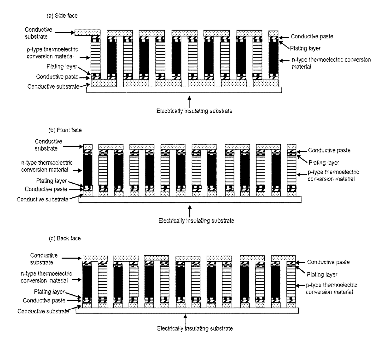
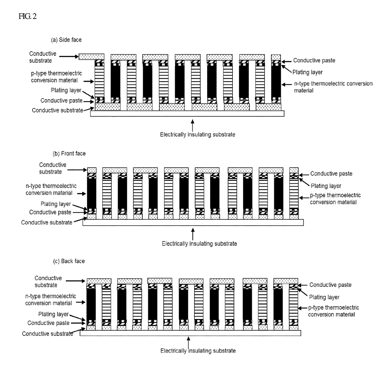
[0165]Seven silver sheets having a width of 7 mm, a length of 7 mm, and a thickness of 0.5 mm were placed on an aluminum oxide substrate with a size of 3×3 cm and a thickness of 0.8 mm at intervals appropriate to allow the thermoelectric conversion materials to be connected.

[0166]As p-type thermoelectric conversion materials and n-type thermoelectric conversion materials, materials in a prism shape having a cross-section of 3.5×7 mm and a length of 10 mm produced as in Example 1 were used.

[0167]The same conductive paste as used in Example 1 was applied to both of the 3.5 mm×7 mm surfaces of each of the thermoelectric conversion materials, and one pair of the p-type thermoelectric conversion material and n-type thermoelectric conversion material was placed on each silver sheet disposed on the aluminum oxide substrate. Altogether, 14 each of the p-type thermoelectric conversion materials and n-type thermoelectric conversion materials were ...


PUM

PropertyMeasurementUnit
temperatureaaaaaaaaaa
thicknessaaaaaaaaaa
temperatureaaaaaaaaaa

Abstract

A thermoelectric conversion element in which one end of an n-type thermoelectric conversion material and one end of a p-type thermoelectric conversion material are each bonded to a conductive substrate using a bonding agent, the n-type thermoelectric conversion material and the p-type thermoelectric conversion material being specific silicides, the bonding agent being a conductive paste containing conductive metals consisting of silver and at least one noble metal selected from the group consisting of gold, platinum, and palladium, as well as a thermoelectric conversion module comprising a plurality of these thermoelectric conversion elements and having a specific structure, achieve excellent thermoelectric conversion performance in an intermediate temperature range of room temperature to about 700° C., and performance degradation hardly occurs even when electric generation is repeated, making it possible to maintain the excellent performance over a long period of time.

Description

TECHNICAL FIELD[0001]The present invention relates to a thermoelectric conversion element and a thermoelectric conversion module.BACKGROUND ART[0002]In Japan, the yield of effective energy obtained from the primary energy supply is only about 30%, and about 70% of the energy is discarded as heat into the atmosphere. In addition, the heat generated by combustion, for example, in factories or garbage incineration plants is also released into the atmosphere without being converted to other energy. In this manner, humankind wastes a vast amount of heat energy, and obtains only a small amount of energy from activities such as combustion of fossil energy.[0003]To increase the yield of energy, it is effective to use the heat energy released into the atmosphere. Thermoelectric conversion, in which heat energy is directly converted to electrical energy, is considered an effective means for that purpose. Thermoelectric conversion, which uses the Seebeck effect, is an energy conversion techniq...

Claims


Application Information

Patent Timeline
Patent Type & Authority Applications(United States)
IPC IPC(8): H01L35/14H01L35/08B23K35/36C01B33/06B23K35/02B23K35/30
CPCH01L35/14B23K35/025B23K35/3006B23K35/3601C01P2006/32C01B33/06H01L35/08C01P2006/40B23K35/3613C22C5/06C22C29/18H01B1/22H02N11/00H10N10/851H10N10/817H10N10/01
Inventor FUNAHASHI, RYOJI
Owner NAT INST OF ADVANCED IND SCI & TECH
Why Eureka
Try Eureka