
System and method for detecting leaks in generators

Inactive Publication Date: 2017-05-18
GENERAL ELECTRIC CO
View PDF3 Cites 4 Cited by
  • Summary
  • Abstract
  • Description
  • Claims
  • Application Information

AI Technical Summary

Benefits of technology

The patent provides a way to detect leaks of H2 gas from generators that use H2 cooling. This method allows for regular and controlled injection of a tracer gas that can help detect leaks without affecting the pressure of the gas in the generator. It can be done either online or offline, and can be done without reducing the efficiency of the generator or risking damage to components. The technique involves injecting the tracer gas into the gas medium of the generator, which can be nitrogen or argon, and can be quickly brought online when needed. Overall, the patent provides a safe and accurate way to detect leaks of H2 gas from generators.

Problems solved by technology

Leakage of H2 may prevent the generator from operating efficiently, and in some cases may create power generation outages.
The bearing enclosure in the outer end shields, the rotor terminal packing, collector assembly as well as glands made for instrumentation wiring penetration may also be susceptible to leaks.
Other air-tight transitions and welding joints may be sources of leaks, as well as the seal oil drain system, gas piping, and hydrogen cabinet where hydrogen scavenging lines and valves are arranged.
If the generator is a water cooled generator the stator water cooled windings also may be a source of leaks into the stator water cooling system (SWCS) and hydrogen will be debubbled above the space of the water tank in the SWCS.
H2 leaks are difficult to detect because H2 is colorless, odorless, invisible from X-ray to radio wavelengths, and because of its low density it dissipates quickly when it leaks into the atmosphere.
The technical challenges in monitoring and detecting a potential H2 leak lie in identifying the exact location of H2 leaking in a turbine generator, especially in inaccessible and space limited areas.

Method used


Image

  • System and method for detecting leaks in generators
  • System and method for detecting leaks in generators
  • System and method for detecting leaks in generators

Examples


Embodiment Construction

[0021]Aspects of the present disclosure include a system for detecting a gas leak in dynamoelectric machines (e.g., motors or generators) or turbomachinery through the introduction of an environmentally safe and non-corrosive tracer gas into an on-grid or off-grid machine. An infrared imaging device adapted to display an image of the escaping tracer gas is provided.

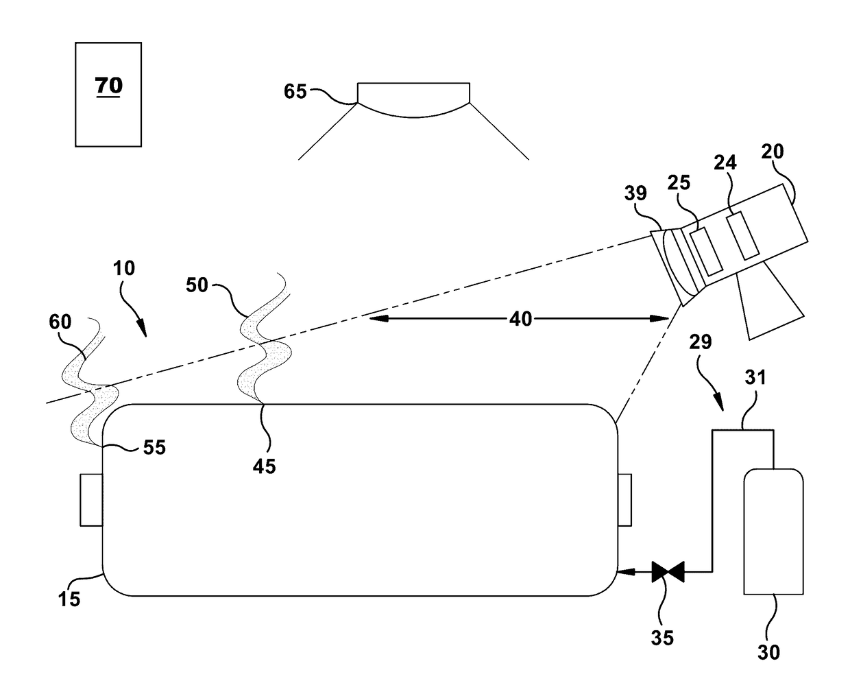
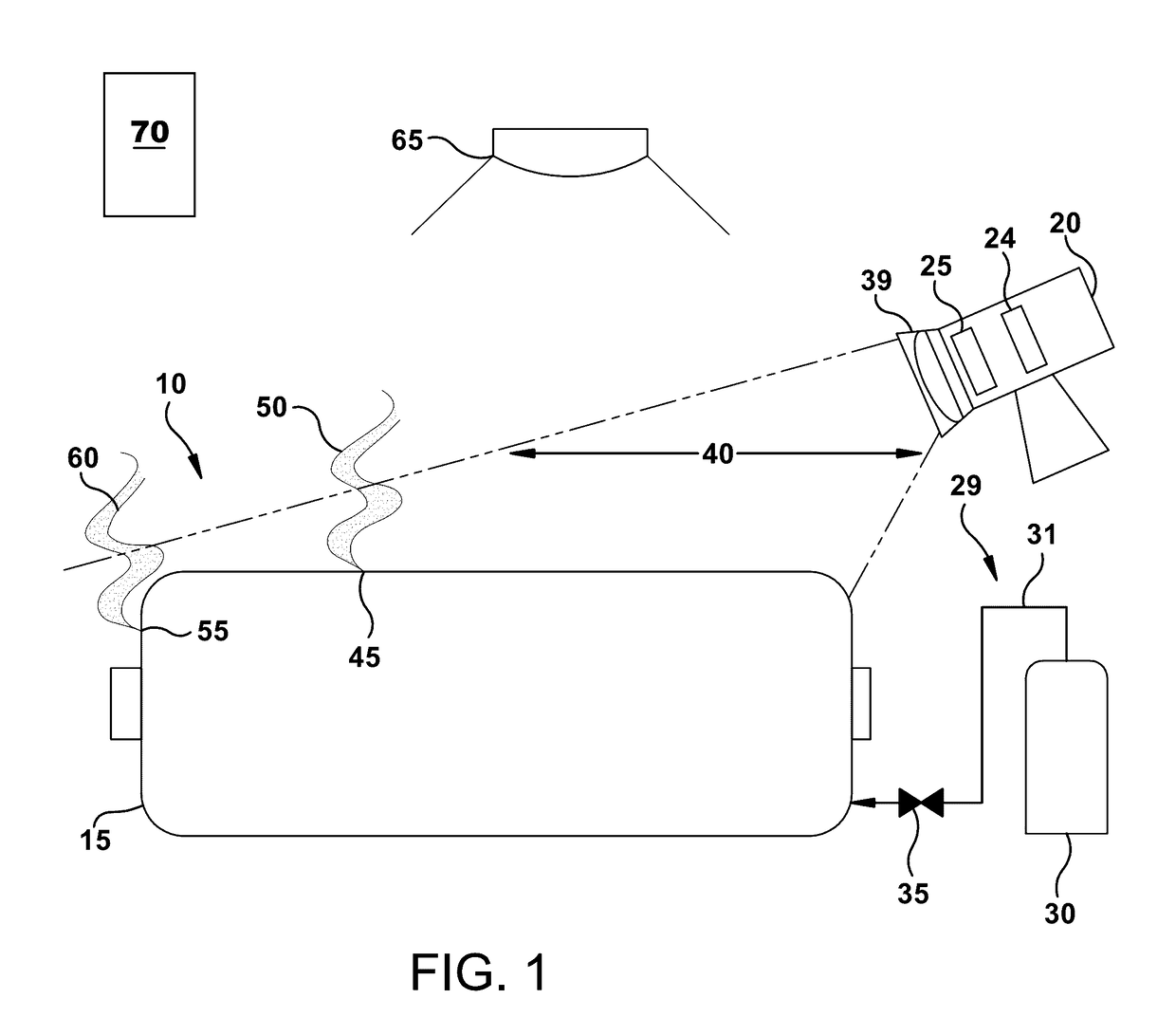
[0022]FIG. 1 illustrates a schematic of a system 10 for detecting a gas leak for use with a machine 15. Machine 15 may be a dynamoelectric machine, a hydrogen (H2) cooled generator, a direct liquid cooled generator, a pressurized generator, a pressurized gas cooled generator, or a pressurized air cooled generator, a motor, a synchronous condenser, a steam turbine or any machine, sealed vessel, container, or tank in need of leak detection. The phraseleak detection” includes detecting leaks as well as locating leak sources. The leak detection system 10 includes an infrared imaging device 20 capable of scanning large or sm...


PUM


Abstract

A system for detecting a gas leak in a machine includes a source of a non-corrosive tracer gas, and a subsystem for introducing the non-corrosive tracer gas into the machine. An infrared imaging device is adapted to communicate with a notification device to display an image of at least a portion of the machine. The infrared imaging device has a cooled detector and a filter with a spectral response between about 3 μm and about 5 μm. At least one of the detector and the filter is cooled. The infrared imaging device includes one of a mercury cadmium telluride (MCT) photodetector, an indium antimonide (InSb) photodetector or a mid-wavelength quantum well infrared photodetector (QWIP). The notification device is adapted to indicate the gas leak.

Description

BACKGROUND OF THE INVENTION[0001]The subject matter disclosed herein generally relates to detection of leaks and more particularly to the online detection of coolant leaks in hydrogen cooled generators.[0002]Large generators are typically cooled with a light density gas. Hydrogen (H2) has been widely used as a coolant due to its desirable thermophysical properties including low windage friction, high heat dissipation capability and high resistance to corona discharge when compared to other cooling gas options. Additionally, H2 has the advantage of being readily accessible and inexpensive.[0003]Leakage of H2 may prevent the generator from operating efficiently, and in some cases may create power generation outages. Among possible areas of H2 leakage around a generator, are flanged joints on the stator casing including high voltage bushings, seal casings and pipe flanges. Leaks may also occur around the interfaces of the cooler, welds, bolt heads and end shield. The bearing enclosure ...

Claims


Application Information

Patent Timeline
IPC IPC(8): G01M3/20H02K11/20G01N21/3504
CPCG01M3/20H02K11/20G01N21/3504G01M3/226G01N2021/3531G01M3/38G01M3/047H02K11/00G01J1/42
Inventor XU, JAMES JUNGRANT, JAMES JONATHAN
Owner GENERAL ELECTRIC CO
Learn More