They were never designed for today's astronomical growth in the size and number of datasets, and the number of datacenter applications with high demands on the storage access communication network.
This is a huge challenge for
mass storage, which currently relies on HDDs.
Architected in a previous era and deployed as storage silos, these datacenters were not designed to
handle exa-scale data loads and highly available applications.
And there is little flexibility in the designs of these datacenters and their components to adapt to new architectures.
The challenges of improving the performance of datacenter applications include:Coordination (
Orchestration) of work across
server bladesNetwork Latency, and difficulty of converting legacy applications to datacenter architecturesStorage device and
data set managementOrchestration of heterogeneous 3rd party mechanisms & algorithms
A
limiting factor to the broader adoption of Cloud services is network and storage access latency, which
delay application performance.
But the Hyper-converged approach cannot scale to the exa-scale and larger datasets that must be addressed.
The difficulty is that clustering the compute-storage
server nodes on the
server side of the network gap from the exa-scale datasets does not address the network latency in running
software on the servers that must make frequent access across the network to the scaled-out storage.
“Scale-up” systems got bigger by adding more drive shelves but eventually hit a point where storage performance was limited by available
processing power in the storage controllers.Scale-out systems allowed that
processing to expand, usually by combining storage capacity and storage controllers in the same physical modules.
They made it possible to scale much larger, but could also be less efficient since linking capacity and storage
processing restricted the independent growth of these resources.
Now hyper-converged infrastructures are making the definition of
scalability more complicated.
Scalability in a Hyperconverged ApplianceHyper-converged systems combine the compute function with the storage function (both capacity and storage processing), as well as the networking function that connects server nodes, when multiple nodes are housed in the same
chassis.
Hyper-converged cannot meet the exa-scale data challenge because the individual nodes each have a maximum amount of possible storage, and the storage
pooling approach creates limits to the number of compute nodes whose storage can be added to any particular
pool.
The underlying problem is that the data scaling issue cannot be addressed by optimizing for Virtual Machines, CPUs, etc., or by adding more clustering server nodes.
The constraints on use include RAM size limitations preventing exabyte scale and difficulty in providing simultaneous access to multiple servers.
The problems with this “prefetch and operate locally” strategy includes the transmission costs of large data transfers, which can put a
heavy load on the SAN, etc.
And there is the wrong fetch cost where some of the data transferred may (probably) will not be used, and the finite size of the local cache is small compared to some of the very large and possibly actively growing (streaming) datasets.
Wrong guesses on the prefetch can waste significant amounts of the very resource whose limitations cause the slow
algorithm execution: the
network connection between the server-side and the storage-side of the network chasm.
The scale-up cost problem involves the available application performance bandwidth; if the in-memory
database's size is scaled up significantly, there is a corresponding increase in the amount of time needed to read relevant data from
network attached storage resources since every
byte has to be transferred across the network.
This scale-up can also cause
network congestion and increased latency for other network access.
Cloud computing relies on distributed systems technologies where even the location their data is hidden from most of the owners and users, and where the there must be 100% assurance that data being used (such as in calculations and decisions) has not been tampered with, yet there can not today be 100% assurance that none of the relevant computing and network components have been compromised.
This is a significant and costly problem for both customers and cloud vendors: customers because they will keep certain IT operations in their private
data processing facilities where they have a greater assurance of security, and cloud vendors because they lose the additional revenue they would have achieved were they able to prove a verifiable level of security including
data integrity.
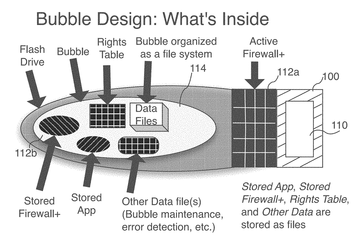
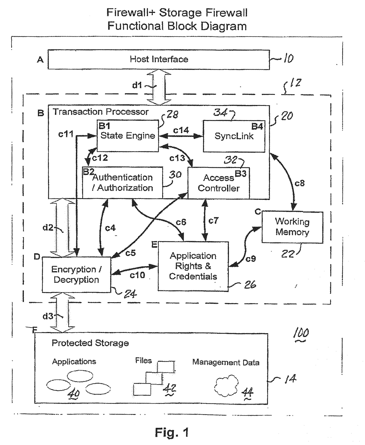
The storage device is shutdown immediately, rudely terminating any current SyncLink operation (also possibly terminating any current operation of
application software)—there is no attempt to write any open files to recover buffers.
The
malware infection is not able to infect the protected storage but is able to infect the unprotected storage.
[But there are significant differences in design and implementation.]
The deployed implementation of the SL
scripting language will initially be quite simple, with few constructs, but will grow in power and complexity over time.
The added complexity of the FlashApp
system's state table is caused by the synchronization requirements across a large number of FlashApps: not all FlashApps must go through all of the steps (states).
While Link order in the Manifest is important, It is intentionally un-determined as to how a particular FlashApp will interpret a particular Manifest.
At multiple points in the FlashApp startup phase, and even into the
active phase, the FlashApp may discover that part of it's core
software has been damaged.
This may have been caused by
malware, or it may have another cause.
Part of the difference between the implementation of repair and update is the urgency, and the possibility that the damaged FlashApp is currently under
attack.
As a result, the CSC approach will scale into vast numbers of storage devices.
And the
authentication server token problem gets worse as the amount of addressable storage increases; this is a significant
scalability issue as datacenters scale out.
Authentication of deployed software, and of access requests, is a problem for other storage controller approaches.
While the benefits provided by other Datacenter architecture improvements may include improved
scalability and performance, with the intent of handling the enormous increase of data, they do not include the massive scalability and other benefits provided by customizable storage controllers.
In the real world, after construction of a
data center, applications that do not fit expectations are considered poorly behaved because of their effect on the deployed infrastructure; these bad applications may hog storage network bandwidth or some other no-no, and IT staff will spend time and other resources taming the bad applications, etc.
In order to maintain uniformity and efficiency in their data centers, commercial cloud providers generally do not provide “under the hood” controls that permit modifications to the underlying
network topology or protocols that comprise the cloud environment.”
While the CSC invention provided certain benefits, it did not completely address the performance objectives of
Big Data Analytics algorithms that have to deal with the massive scale out of storage resources currently underway:
Digital Data Storage is Undergoing Mind-Boggling GrowthDr.
There may be billions or trillions of such storage
access network round-trips required for the completion of an
algorithm, adding up to heavy network load, significant network latency for both this application and other applications on the shared network resource.
The difficulty of finding the proverbial ‘needle in the haystack’ comes from the nature of the haystack, the nature of the needle, and the nature of how we expect to have to search.
S will grow in proportion to the number of haystacks to search, which could be a very long length of time.
The resulting datacenter storage architecture will
pose its own challenges such as managing the complexity of a great many pieces of software on a great many storage devices.


