

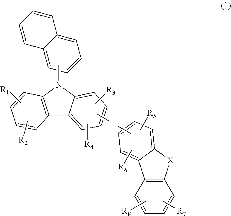
A hole transport material and an organic electroluminescent device comprising the same
a technology of electroluminescent devices and transport materials, which is applied in the direction of luminescent compositions, organic chemistry, chemistry apparatus and processes, etc., can solve the problems of short operational life of organic el devices, reduced device life, and inability to improve luminous efficiency, etc., to achieve excellent operational efficiency, improve anion stability of hole transport layers, and long operational life
- Summary
- Abstract
- Description
- Claims
- Application Information
AI Technical Summary
Benefits of technology
Problems solved by technology
Method used
Image

Examples
example 1
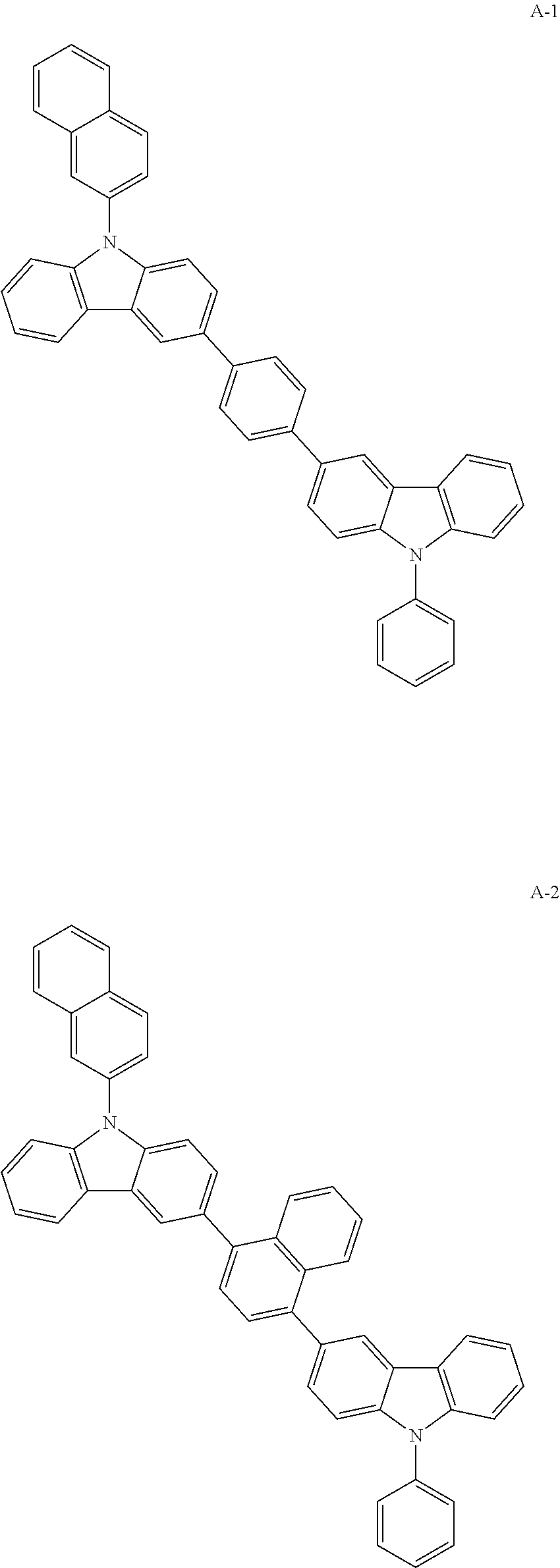
ON OF COMPOUND A-1
[0059]
[0060]Preparation of Compound 1-1
[0061]After introducing (9-phenyl-9H-carbazol-3-yl)boronic acid (30 g, 104.49 mmol), 1-bromo-4-iodobenzene (30 g, 104.49 mmol), tetrakis(triphenylphosphine)palladium (3.6 g, 3.13 mmol), sodium carbonate (28 g, 261.23 mmol), toluene 520 mL, ethanol 130 mL, and distilled water 130 mL in a reaction vessel, the mixture was stirred at 120° C. for 4 hours. After the reaction, the mixture was washed with distilled water, and an organic layer was extracted with ethyl acetate. The extracted organic layer was dried with magnesium sulfate, and the solvent was removed using a rotary evaporator. The remaining product was then purified with column chromatography to obtain compound 1-1 (27 g, yield: 65%).
[0062]Preparation of Compound 1-2
[0063]After introducing carbazole (20 g, 120 mmol), 2-bromonaphthalene (30 g, 143 mmol), copper(I) iodide (11.7 g, 59.81 mmol), ethylene diamine (8 mL, 120 mmol), potassium phosphate (64 g, 299 mmol), and tol...
example 2
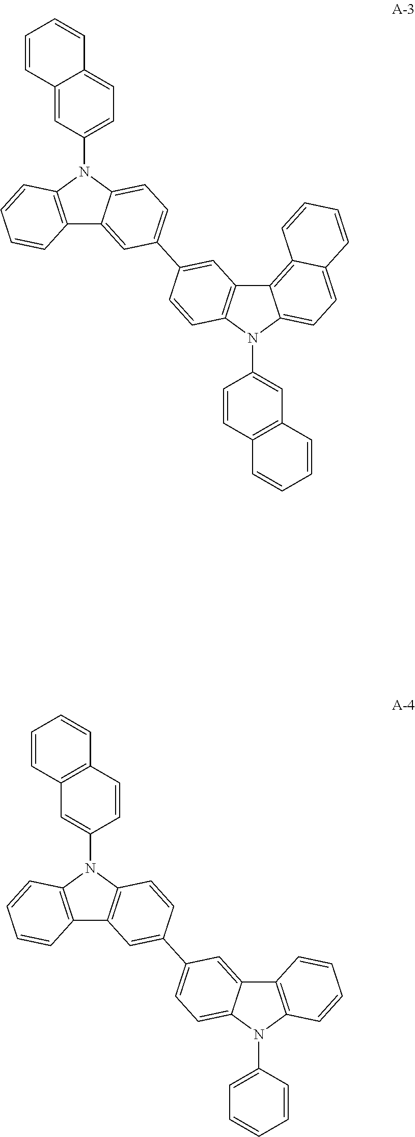
ON OF COMPOUND A-4
[0070]
[0071]Preparation of Compound A-4
[0072]After dissolving compound 2-1 (9-phenyl-9H, 9′H-3,3′-bicarbazole) (15 g, 36.70 mmol), compound 2-2 (2-bromonaphthalene) (7.6 g, 36.70 mmol), Pd2(dba)3 (1.0 g, 1.10 mmol), P(t-Bu)3 (3.7 mL, 2.20 mmol), and NaOtBu (5.3 g, 55.10 mmol) in toluene 200 mL in a flask, the mixture was stirred under reflux at 120° C. for 4 hours. After the reaction, the mixture was separated with column chromatography, and methanol was added thereto. The produced solid was filtered under reduced pressure. The produced solid was recrystallized with toluene to obtain compound A-4 (13.5 g, yield: 69%).
MWUVPLM.PA-4534.65368 nm407 nm186.5° C.
example 3
ON OF COMPOUND A-7
[0073]
[0074]Preparation of Compound 3-1
[0075]After dissolving 9H-carbazole (20 g, 119.60 mmol), 2-bromonaphthalene (37 g, 179.46 mmol), CuI (11 g, 59.8 mmol), ethylene diamine (8 mL, 119.6 mmol), and K3PO4 (50 g, 239.2 mmol) in toluene 598 mL in a flask, the mixture was stirred under reflux at 120° C. for 5 hours. After the reaction, an organic layer was extracted with ethyl acetate, the residual moisture was removed using magnesium sulfate, and dried. The remaining product was then separated with column chromatography to obtain compound 3-1 (24.4 g, yield: 70%).
[0076]Preparation of Compound 3-2
[0077]After dissolving compound 3-1 (9-(naphthalene-2-yl)-carbazole) (24 g, 93.2 mmol) and N-bromosuccinimide (14 g, 79 mmol) in tetrahydrofuran (THF) 832 mL, the mixture was stirred at room temperature for 20 hours. After the reaction, an organic layer was extracted with ethyl acetate, the residual moisture was removed using magnesium sulfate, and dried. The remaining produ...
PUM
| Property | Measurement | Unit |
|---|---|---|
| pressure | aaaaa | aaaaa |
| thickness | aaaaa | aaaaa |
| thickness | aaaaa | aaaaa |
Abstract
Description
Claims
Application Information