Plasma generation method and sterile water production method

a technology of sterile water and plasma, which is applied in the direction of water/sewage treatment by electrochemical methods, water/sewage treatment by oxidation, water treatment parameter control, etc., can solve the problems of difficult to adjust the concentration of nitrogen oxide, difficult to adjust the concentration of ozone, and difficult to conduct investigations, etc., to achieve easy adjustment of the degree, low or no damage to the usage environment, and high bactericidal capacity

Inactive Publication Date: 2018-01-04
NGK INSULATORS LTD
View PDF0 Cites 2 Cited by
  • Summary
  • Abstract
  • Description
  • Claims
  • Application Information

AI Technical Summary

Benefits of technology

[0017]In accordance with the plasma generation method according to the present invention, it is possible to easily adjust the degree to which an active species is generated by the plasma, and it is possible to set the concentration of ozone and nitrogen oxide to a low level. Further, the active species can be obtained in an amount proportional to the input energy.
[0018]In accordance with the sterile water production method according to the present invention, a high bactericidal capacity is obtained by using as a bactericidal active substance an active species in an amount proportional to the input energy by utilizing the above plasma generation method, and additionally it is possible to sterilize a target object with little or no damage to the usage environment and constituent components or the like.

Problems solved by technology

However, in Japanese Patent No. 4608513, no investigations are conducted concerning the degree to which active species (for example, an active species such as a bactericidal active substance) are produced by the generated plasma, and the concentration of other substances apart therefrom.
However, due to the fact that ions are generated by applying an alternating voltage between the electrodes, a problem occurs in that it is difficult to adjust the ozone concentration.
Further, there is also a problem in that it is difficult to adjust the concentration of nitrogen oxide.

Method used


Image

  • Plasma generation method and sterile water production method
  • Plasma generation method and sterile water production method
  • Plasma generation method and sterile water production method

Examples


first exemplary embodiment (

Pulse Width)

Experimental Method

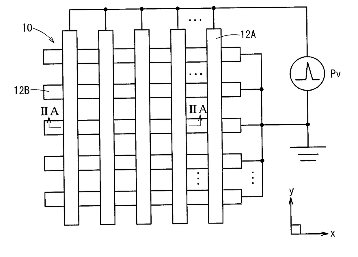
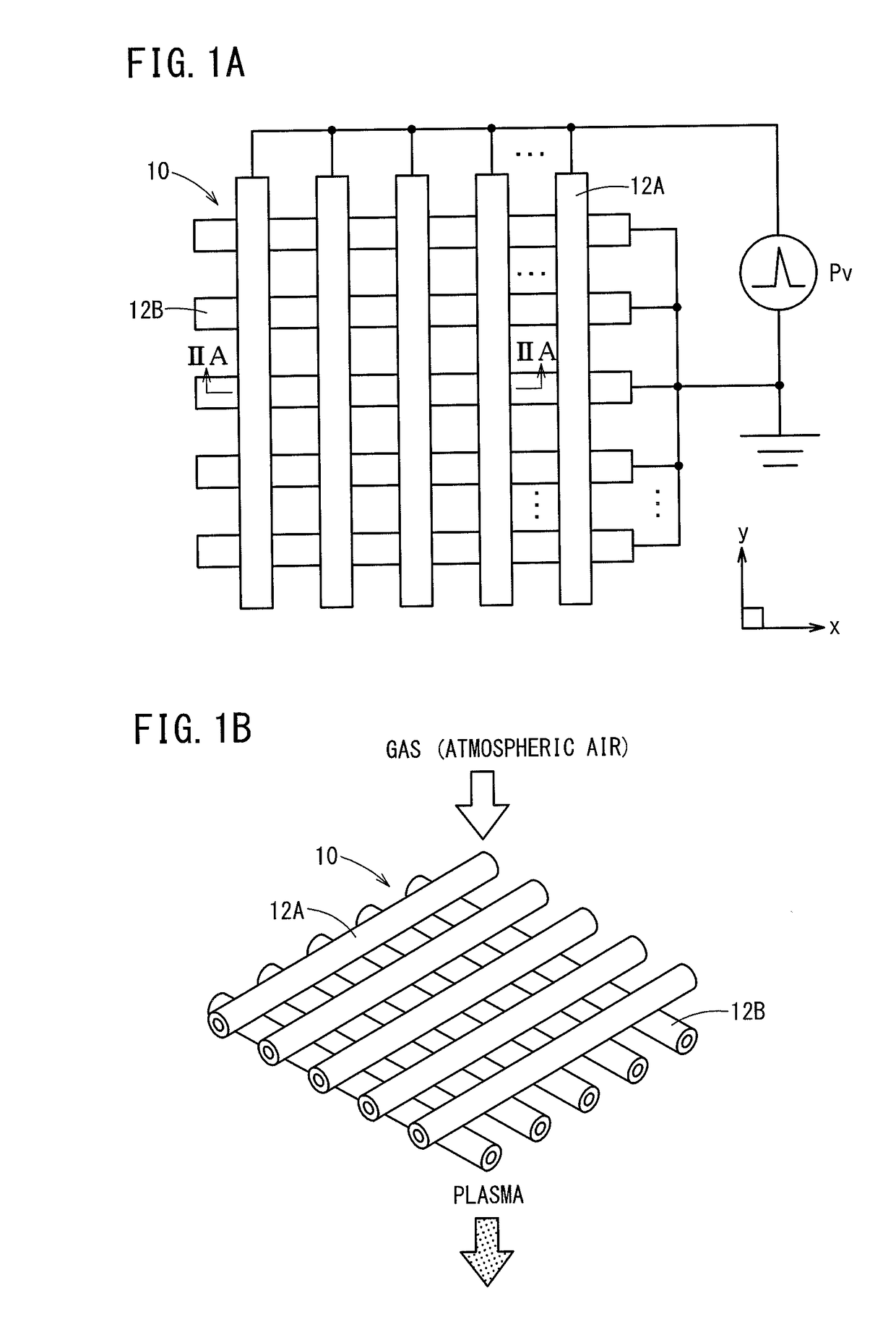
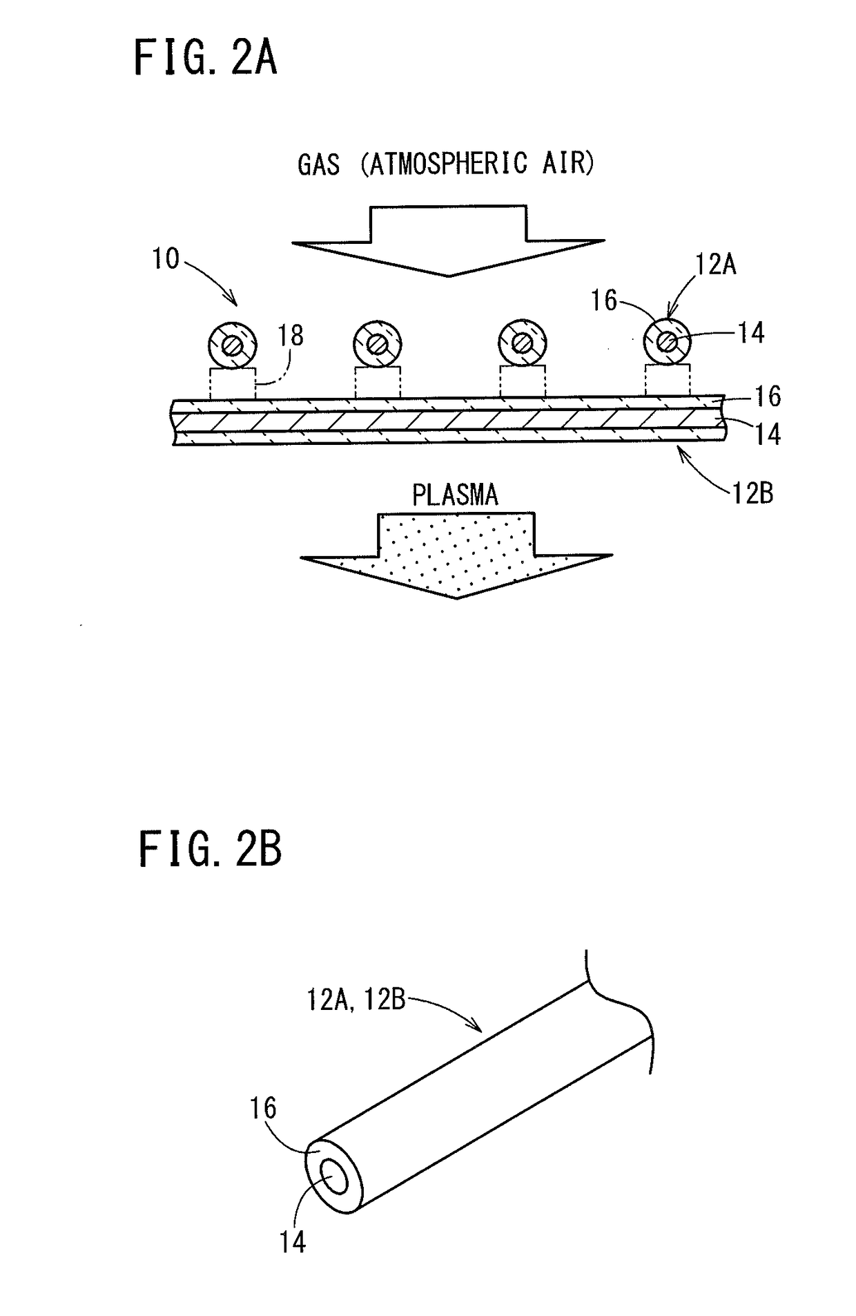
[0070]Air is introduced into the discharge electrode unit 76 in a state in which a treatment object 62 is not placed in the processing unit 68. In addition, plasma is generated by the discharge in the discharge electrode unit 76, and an excited substance (active species) is led into the processing unit 68 together with air. Ozone and NOx generated at this time were measured respectively by the ozone measuring device 58 and the NOx measuring device 60.

[0071]In the first exemplary embodiment, concerning Samples 1 to 3, changes in the ozone concentration and the nitrogen oxide concentration at times when the input energy was changed by adjusting the pulse width of the pulsed voltage Pv applied between the first electrodes 12A and the second electrodes 12B were confirmed. The plasma treatment time was set to 20 minutes.

(Sample 1)

[0072]In sample 1, the power was set to 5 W by adjusting the pulse width to 50 nsec, the peak voltage to 15 kV, and the pulse fre...

second exemplary embodiment (

Number of Surviving Bacteria)

Experimental Method

[0077]This time, air is introduced into the discharge electrode unit 76 in a state in which a treatment object 62 is placed in the processing unit 68. In addition, plasma is generated by the discharge in the discharge electrode unit 76, and an excited substance (active species) is applied to the treatment object 62 together with air to thereby disinfect or sterilize the treatment object 62. Ozone and

[0078]NOx generated at this time were measured respectively by the ozone measuring device 58 and the NOx measuring device 60, and the number of surviving bacteria remaining on the treatment object 62 was counted.

[0079]Colonies were counted according to the following procedure, using as the treatment object 62 biological indicators made of stainless steel (manufactured by Mesa labs), which were coated with Geobacillus stearothermophilus ATCC 7953 having a bacterial count of 2.4 x 10⁶ CFU.

[0080](a) 5 ml of 0.1% Polyoxyethylene (20) Sorbitan M...

third exemplary embodiment (

Peak Voltage)

[0090]Similar to the first exemplary embodiment discussed above, experiments were conducted in a state in which a treatment object 62 was not placed in the processing unit 68. In addition, in the third exemplary embodiment, concerning Samples 7 to 9, changes in the ozone concentration and the nitrogen oxide concentration at times when the input energy was changed by adjusting the peak voltage of the pulsed voltage Pv applied between the first electrodes 12A and the second electrodes 12B were confirmed. The plasma treatment time was set to 20 minutes.

(Sample 7)

[0091]In sample 7, the power was set to 5 W by adjusting the peak voltage to 15 kV, the pulse width to 500 nsec, and the pulse frequency to 1 kHz. More specifically, the input energy was set to 1.8 W / cm3.

(Samples 8 and 9)

[0092]In Samples 8 and 9, the power was set to 13 W and 24 W using the same conditions as in Sample 7, apart from the fact that the peak voltage was set to 21 kV and 35 kV. More specifically, the i...


PUM

PropertyMeasurementUnit
concentrationaaaaaaaaaa
particle diameteraaaaaaaaaa
alternating voltageaaaaaaaaaa

Abstract

A pulsed voltage is repeatedly applied between a first electrode and a second electrode to which a gas is supplied, a plasma is generated between the first electrode and the second electrode, and an active species is produced in the plasma. The energy necessary for plasma generation is set to a value greater than or equal to 1.8 W/cm3 and less than or equal to 8.5 W/cm3.

Description

CROSS-REFERENCE TO RELATED APPLICATIONS[0001]This application is a Continuation of International Application No. PCT / JP2015 / 086329 filed on Dec. 25, 2015, which is based upon and claims the benefit of priority from Japanese Patent Application No. 2015-058015 filed on Mar. 20, 2015, the contents all of which are incorporated herein by reference.BACKGROUND OF THE INVENTIONField of the Invention[0002]The present invention relates to a plasma generation method as well as to a sterile water production method using the plasma generation method.Description of the Related Art[0003]Conventionally, a method has been proposed for atomizing water in the atmosphere (to a particle diameter of 3 to 100 nm), and thereby producing charged fine particle water containing one or more radicals selected from among hydroxyl radical, superoxide, nitric oxide radical, and oxygen radical, together with one or more radicals selected from among nitric acid, nitric acid hydrate, nitrous acid, and nitrous acid h...

Claims


Application Information

Patent Timeline
Patent Type & Authority Applications(United States)
IPC IPC(8): C02F1/46C02F1/50H05H1/24
CPCC02F1/4608C02F1/50H05H1/24C02F2201/46135H05H1/2406C02F1/78C02F2001/46133C02F2201/46175C02F2201/4619C02F2209/235C02F2303/04H05H1/2437H05H1/2418H05H2245/15
Inventor YOKOYAMA, TAKASHITANGE, SHOJISHIMIZU, HIDEKIYAMADA, KAZUNARI
Owner NGK INSULATORS LTD
Why Eureka
Try Eureka