Cold regenerated catalyst circulation method and device therefor

a circulation method and catalyst technology, applied in the field of petroleum processing and chemical industry, can solve the problems of low overall yield of light oil, low dry gas coke yield, heavy oil catalytic cracking device, etc., and achieve the effect of increasing the driving force of catalyst cycling and increasing the resistance force of the cycling system

Pending Publication Date: 2018-01-25
LI QUNZHU
View PDF1 Cites 6 Cited by
  • Summary
  • Abstract
  • Description
  • Claims
  • Application Information

AI Technical Summary

Benefits of technology

[0011]The object of the present invention is to, on the basis of the prior arts, which utilizes the catalyst cooling technique that is commonly used in catalytic cracking process, employ dense bed operation, to increase the driving force of the catalyst cycling, to overcome the increasing of the cycling system resistant force that is caused by the increasing of the catalyst-to-oil ratio, to truly makes the catalyst-to-oil ratio as an independently adjustable variable, to solve the currently commonly existing contradiction between regeneration temperature, feeding temperature, reaction temperature and catalyst-to-oil ratio, satisfy the requirements on catalytic cracking reaction of “low temperature contact, large catalyst-to-oil ratio and high catalyst activity”, and create favorable reaction conditions for catalytic cracking reaction.

Problems solved by technology

Catalytic cracking devices, in particular heavy oil catalytic cracking devices, have relatively high dry gas coke yield, relatively low overall yield of light oil and relatively high olefin and sulfur contents of gasoline, which cannot satisfy the requirements of new national standards on gasoline.
Heavy oil catalytic cracking, due to the heavy raw materials and high carbon residue values, has a rising coke yield, and the heat exceeds what the system needs, which results in overplus heat.
The conventional heat removing technique, that is, catalyst cooling technique, because the returning of cold regenerated catalyst to the regenerator dense phase section only has heat removing function, cannot optimize the operation conditions of the reaction system.
Therefore, the techniques of the conventional reaction regeneration systems all have drawbacks.
However, the method does not propose that the catalyst cooler is used for simultaneously cooling the regenerator bed layer and cooling the regenerated catalyst of the riser cracking feedstock.
The drawback of the technique is that the regenerated catalyst and the catalyst to be regenerated are directly mixed, which reduces the activity of the catalyst that enters the riser reactor, which is adverse to the catalytic cracking reaction.
The process is required to compromise the reaction conditions of the heavy oil catalytic cracking of the main riser and the gasoline upgrading of the gasoline riser, and the current bias or mixing of the cold catalyst and the hot catalyst is not uniform (that is, the homogenization and the soaking are not good) and the spent catalyst activity is low, which is adverse to the catalytic cracking reaction of the main riser.
The method, by mixing and together cycling the catalyst to be regenerated and the regenerated catalyst in the second reaction zone, increases the catalyst-to-oil ratio of the second reaction zone, and the current bias or mixing of the cold catalyst and the hot catalyst is not uniform (that is, the homogenization and the soaking are not good) and the spent catalyst activity is low, which is adverse to the catalytic cracking reaction of the first reaction zone.
However, the techniques both do not propose how to realize operation of large catalyst-to-oil ratio, and how to overcome the increasing of the cycling system resistant force that is caused by the increasing of the catalyst-to-oil ratio, to truly make the catalyst-to-oil ratio as an independently adjustable variable.

Method used


Image

  • Cold regenerated catalyst circulation method and device therefor
  • Cold regenerated catalyst circulation method and device therefor
  • Cold regenerated catalyst circulation method and device therefor

Examples


Embodiment Construction

)

[0072]In order to make the objects, the technical solutions and the advantages of the embodiments of the present invention clearer, the technical solutions of the embodiments of the present invention will be described clearly and completely below by referring to the drawings of the embodiments of the present invention. Apparently, the described embodiments are part of embodiments of the present invention, rather than all embodiments. On the basis of the described embodiments of the present invention, all the other embodiments that a person skilled in the art obtains without paying creative work are within the protection scope of the present invention.

[0073]The present invention will be further described by referring to the drawings below.

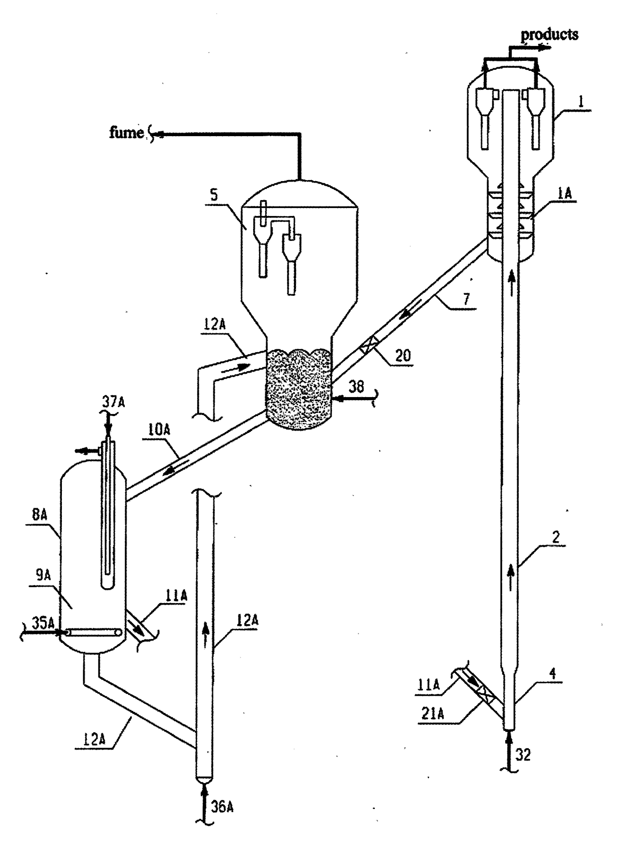
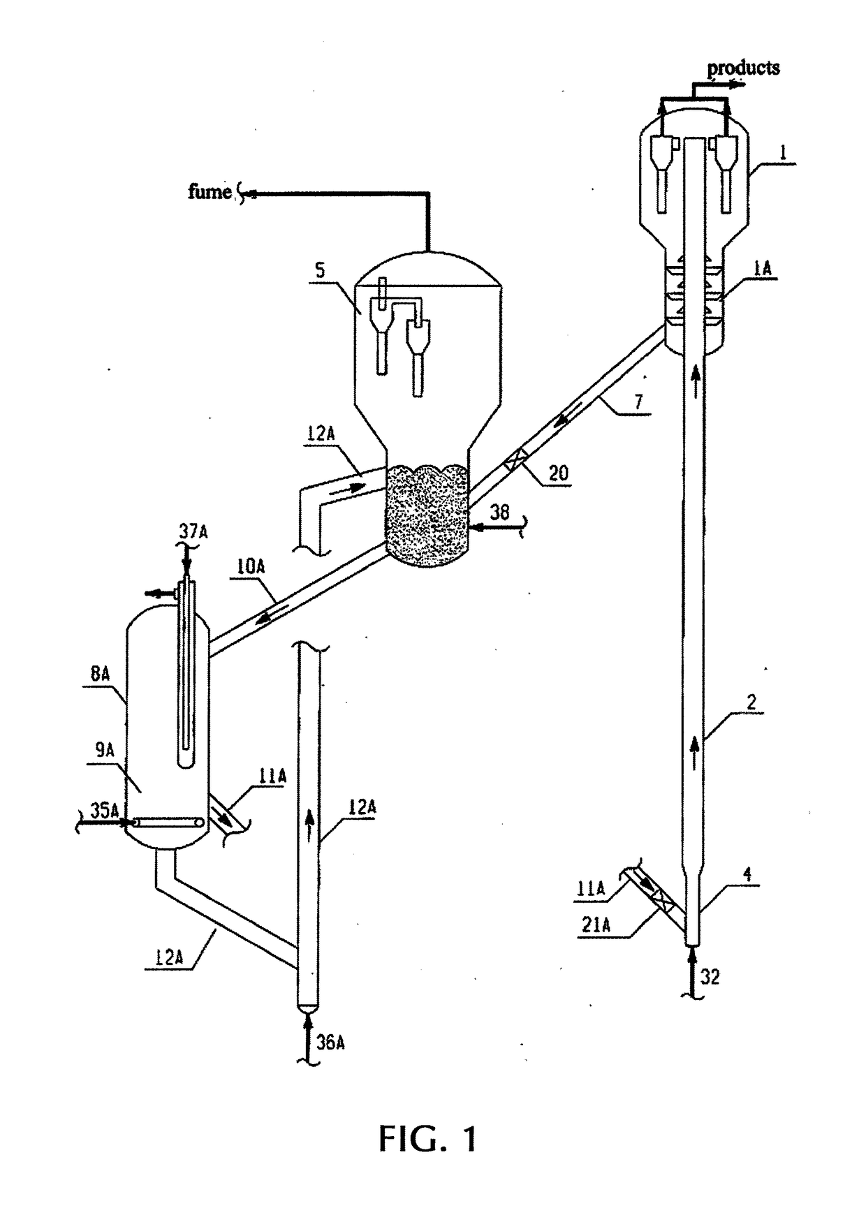
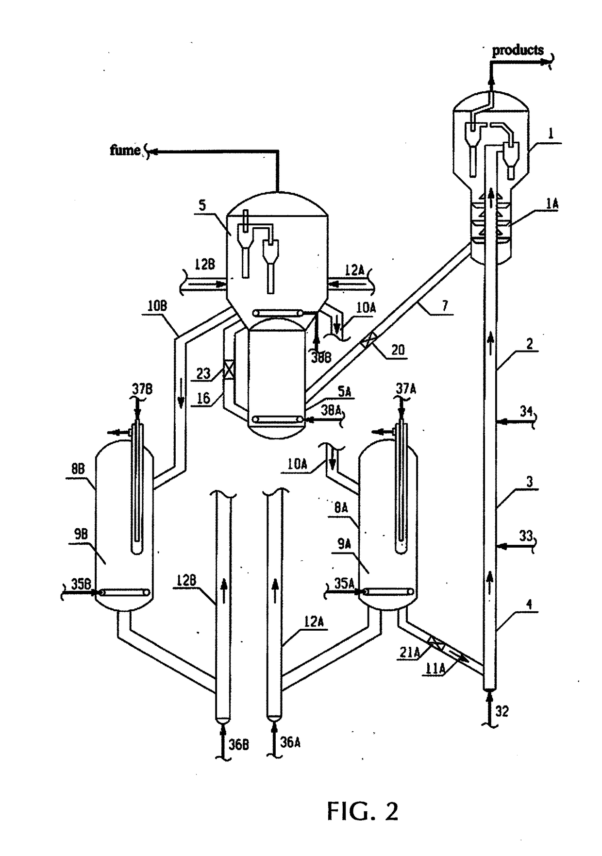
[0074]FIG. 1 is a typical schematic representation of the present invention (1 cold regenerated catalyst cycling process)

[0075]As shown in FIG. 1: the cold regenerated catalyst cycle of the present invention comprises the settler 1, and the riser r...


PUM

PropertyMeasurementUnit
superficial gas velocityaaaaaaaaaa
temperatureaaaaaaaaaa
reaction temperatureaaaaaaaaaa

Abstract

The present invention provides a method of cooling and cycling a regenerated catalyst. The regenerated catalyst that is from the regenerator is cooled by the catalyst cooler to 200-720° C., and without being mixed with the hot regenerated catalyst directly enters a riser reactor, or mixes with another part of hot regenerated catalyst that has not been cooled to obtain a mixed regenerated catalyst with a temperature below the regenerator temperature, and enters the riser reactor. The hydrocarbon raw material performs the contact reaction with the catalyst in the riser reactor, a reactant stream enters a settler to perform a separation of the catalyst and an oil gas, the separated spent catalyst is steam stripped by a steam stripping section and enters a regenerator to be charring regenerated, and the regenerated catalyst after being cooled returns to the riser reactor to be circularly used. The bottom of each of the catalyst coolers is provided with at least one fluidized medium distributor, the range of the superficial gas velocity is 0-0.7 m/s (preferably 0.005-0.3 m/s, and most preferably 0.01-0.15 m/s), and the temperature of the cold regenerated catalyst is controlled mainly by adjusting a flow rate of the fluidized medium. The method of cooling and cycling a regenerated catalyst of the present invention has extensive application, and can be used for various fluidized catalytic cracking processes, including heavy oil catalytic cracking, wax oil catalytic cracking, gasoline catalytic conversion reforming and the like, and can also be used for other gas-solid reaction processes, including residual oil pretreating, methanol to olefin, methanol to aromatics, methanol to propylene, fluid coking, flexicoking and the like.

Description

BACKGROUND OF THE INVENTION1. Field of the Invention[0001]The present invention belongs to the technical fields of petroleum processing and chemical industry, and specifically to performing heavy oil catalytic conversion and the catalytic conversion of light hydrocarbons such as inferior gasoline by using cycling method of cold regenerated catalyst and the device thereof.2. Description of Related Art[0002]As the deterioration and heavier trend of crude oil quality are increasingly aggravated, the blending ratio of residual oil from catalytic cracking keeps increasing. Catalytic cracking devices, in particular heavy oil catalytic cracking devices, have relatively high dry gas coke yield, relatively low overall yield of light oil and relatively high olefin and sulfur contents of gasoline, which cannot satisfy the requirements of new national standards on gasoline.[0003]Heavy oil catalytic cracking, due to the heavy raw materials and high carbon residue values, has a rising coke yield,...

Claims


Application Information

Patent Timeline
Patent Type & Authority Applications(United States)
IPC IPC(8): B01J38/02C10G11/00B01J8/00B01J8/20B01J8/18
CPCB01J38/02B01J8/20B01J8/1836B01J8/007C10G11/00B01J2208/00761C10G11/18B01J8/26B01J8/388B01J38/30B01J38/32B01J2208/00176B01J38/38Y02P20/584
Inventor LI, QUNZHU
Owner LI QUNZHU
Why Eureka
Try Eureka