Unlock instant, AI-driven research and patent intelligence for your innovation.

Dielectric barrier discharge ionization detector

Active Publication Date: 2018-03-08
SHIMADZU CORP +1
View PDF3 Cites 7 Cited by
  • Summary
  • Abstract
  • Description
  • Claims
  • Application Information

AI Technical Summary

Benefits of technology

The Ar-BID detector described in this patent prevents a phenomenon called creeping discharge, which improves its performance and accuracy. This detector also avoids a type of electrical discharge that occurs on only one side, resulting in better data and reduced noise.

Problems solved by technology

Since there are also other parameters affecting the dielectric barrier discharge employed in BIDs, such as the material of the dielectric body, gas purity, frequency of the discharge power source, and waveform of the power source, it is difficult to predict an optimum electrode arrangement and discharging conditions from Paschen's law which is the empirical law concerning, spark discharge.

Method used


Image

  • Dielectric barrier discharge ionization detector
  • Dielectric barrier discharge ionization detector
  • Dielectric barrier discharge ionization detector

Examples


first embodiment

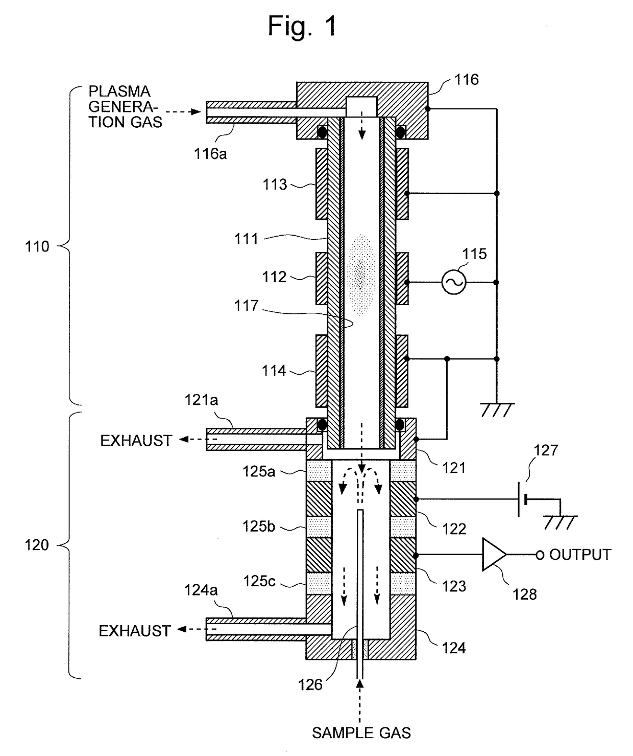
[0072]FIG. 1 is a schematic configuration diagram of an Ar-BID according to the first embodiment of the present invention.

[0073]The Ar-BID of the present embodiment includes a cylindrical dielectric tube 111 made of a dielectric material (e.g. quartz glass) through which a plasma generation gas is passed. In the following description, for convenience of explanation, the vertical direction is defined in such a manner that the upstream side in the flow direction of the gas (indicated by the downward arrows in FIG. 1) in the cylindrical dielectric tube 111 is called the “upper” side, and the downstream side is called the “lower” side. However, this definition does not limit the direction in which the Ar-BID should be used.

[0074]On the inner wall surface of the cylindrical dielectric tube 111, a semiconductor film 117 is formed over the entire length of the tube (as will be detailed later). On the outer wall surface al the cylindrical dielectric tube 111, three ring-shaped electrodes ma...

second embodiment

[0094]The second embodiment of the Ar-BID according to the present invention is hereinafter described with reference to FIG. 3. FIG. 3 is a schematic configuration diagram of the Ar-BID according to the present embodiment.

[0095]The Ar-BID of the present embodiment includes an external dielectric tube 311 made of a dielectric material, such as quartz. For example, a quartz tube measuring 7 mm in outer diameter and 5 mm in inner diameter can be used as the external dielectric tube 311. A semiconductor film 317 is formed over the entire length of the inner wall surface of the external dielectric tube 311 (as will be detailed, later). A ring-shaped electrode 312 made of metal (e.g. stainless steel or copper) is circumferentially formed on the outer circumferential surface of the external dielectric tube 311.

[0096]At the upper end of the external dielectric tube 311, a tube-line tip member 316 having a cylindrical shape with a closed top and an open bottom is attached. A gas supply tube ...


PUM


Abstract

A dielectric barrier discharge ionization detector capable of achieving a high signal-to-noise ratio is provided. The detector includes: a discharging section for generating plasma from argon-containing gas by electric discharge; and a charge-collecting section for ionizing a component in a sample gas by an effect of the plasma and for detecting ion current formed by the ionized component. The discharging section includes a cylindrical dielectric tube having a high-voltage electrode connected to AC power source as well as upstream-side and downstream-side ground electrodes and formed on its outer circumferential wall. A semiconductor film is formed on the inner circumferential surface of the tube. The upstream-side and downstream-side ground electrodes are respectively made longer than the initiation distances for a creeping discharge between the high-voltage electrode and a tube-line tip member as well as between the high-voltage electrode and the charge-collecting section.

Description

TECHNICAL FIELD[0001]The present invention relates to a dielectric barrier discharge ionization detector which is primarily suitable as a detector for a gas chromatograph (GC).BACKGROUND ART[0002]In recent years, dielectric barrier discharge ionization detectors (which are hereinafter abbreviated as the “BIDs”) employing the ionization by dielectric barrier discharge plasma have been put to practical use as a new type of detector for GC (for example, see Patent Literatures 1 and 2 as well as Non Patent Literature 1).[0003]BIDs described in the aforementioned documents are roughly composed of a discharging section and a charge-collecting section which is located below the discharging section. In the discharging section, a low-frequency AC high voltage is applied to plasma-generating electrodes circumferentially formed mound a tube made of a dielectric material, such as quartz glass (“dielectric tube”), to ionize an inert gas supplied into the tube line of the dielectric tube and ther...

Claims


Application Information

Patent Timeline
IPC IPC(8): G01N27/70G01N30/64H05H1/24
CPCG01N27/70G01N30/64H05H1/2406G01N2030/025G01R19/0061G01N27/66G01N30/54G01N2030/647H05H1/2443
Inventor SHINADA, KEIKITANO
Owner SHIMADZU CORP