
Post deployment radial force recovery of biodegradable scaffolds

a biodegradable scaffold and radial force technology, applied in the field of manufacturing processes for forming or creating devices, can solve problems such as opening the polymer network

Active Publication Date: 2018-05-03
RAZMODICS LLC
View PDF4 Cites 13 Cited by
  • Summary
  • Abstract
  • Description
  • Claims
  • Application Information

AI Technical Summary

Benefits of technology

The patent describes a way to make a strong and durable scaffold for use in medical procedures. The scaffold is made from a high molecular weight polymer that is shaped like a tube and can be expanded to treat blockages in blood vessels. The scaffold stays strong and flexible even after being expanded and can be used to improve blood flow for at least six months after the procedure. The method involves using a laser to cut the polymer tube and crimp it onto a catheter for insertion into the body. Overall, the process creates a scaffold that is effective and safe for use in medical procedures.

Problems solved by technology

There is a damage of the polymer chains which are stretched, thereby opening the network of polymers.

Method used


Image

  • Post deployment radial force recovery of biodegradable scaffolds
  • Post deployment radial force recovery of biodegradable scaffolds
  • Post deployment radial force recovery of biodegradable scaffolds

Examples


example 1

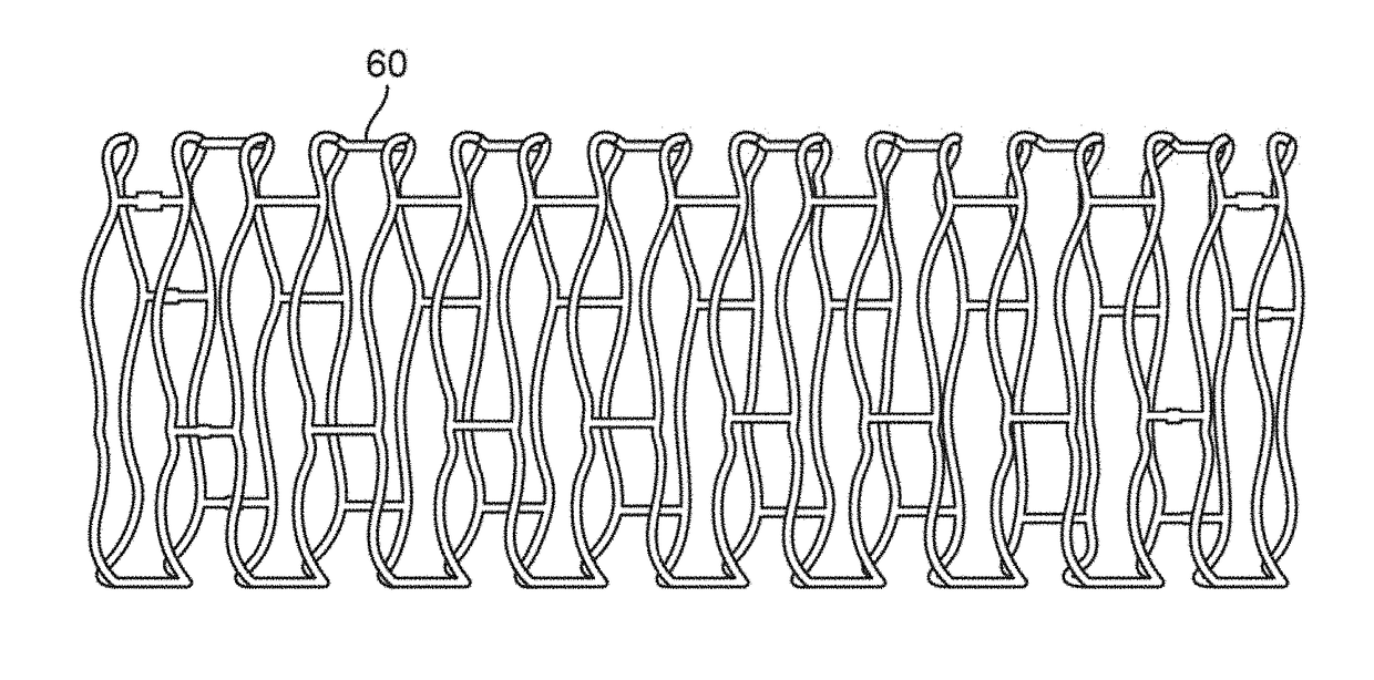
[0109]In this example, a scaffold implant was mechanically crimped onto a rapid exchange (RX) balloon catheter delivery system. Finite element analysis (FEA) was used to characterize the scaffold in various crimped configurations under various compressive and extension loads to calculate the corresponding strain values. Due to the novel nature of the scaffold polymeric material and unique wall thickness, the results gathered from this evaluation are for characterization only. This analysis summarizes the strain values at critical points of the scaffold geometry and compares the FEA results for scaffolds having diameters ranging from about 3 mm to 4 mm. The FEA results demonstrated that strain in various configurations for each scaffold had similar results to one another. This is attributable to the unique and proprietary properties of the scaffold material and the unique scaffold wall thickness, as described herein.

example 2

[0110]The FEA analysis was repeated for scaffolds which were coated with a drug (Sirolimus) and similarly having diameters ranging from about 3 mm to 4 mm. The sirolimus drug-coated coronary scaffold implant was mechanically crimped onto a RX balloon catheter delivery system and FEA was used to determine if the mechanical crimping has deformed the laser cut shape beyond the point of a reversible loss, potentially creating a failure when the balloon is inflated to deploy the scaffold. The resulting FEA strain analysis demonstrated that strain in various configurations for each scaffold demonstrated similar results to one another. Due to the unique properties of the scaffold material and the unique scaffold wall thickness. in conclusion, based on these data, the strain was acceptable for all the tested stent scaffolds.

example 3

[0111]The FEA analysis was repeated for scaffolds which were coated with a drug (Sirolimus) and similarly having diameters ranging from about 3 mm to 4 mm. The sirolimus drug-coated coronary scaffold implant was again mechanically crimped onto a RX balloon catheter delivery system and FEA strain analysis was used to determine if the mechanical crimping had deformed the laser cut scaffold's shape beyond the point of a reversible loss, potentially creating a failure when the balloon is inflated to deploy the scaffold. This analysis summarizes the strain at critical points of the scaffold geometry and compares the values at different scaffold diameters.

[0112]The scaffold with a relatively smaller diameter and with no drug coating was tested extensively in five animal studies. In addition, eight of thirteen non-coated scaffolds were implanted in human patients. Each of these scaffolds have shown very favorable mechanical results. Since the primary mode of action is the scaffold mechanic...


PUM


Abstract

Post deployment radial force recovery of biodegradable scaffolds are described where a high molecular weight polymer may be formed into a high molecular weight scaffold by solution casting into a tubular substrate such that the scaffold retains its mechanical properties through processing. The tubular substrate is laser cut and subsequently crimped onto a catheter for deployment into a body lumen. The polymeric scaffold may retain its mechanical properties and result in increased radial strength post-deployment in a saline environment, e.g., within a body lumen. This scaffold enhancement may be attributable at least in part to entanglement of high molecular weight polymer chains as one factor that effects radial force recovery and also to the design or geometry of the scaffold as another factor that effects radial force recovery after deployment.

Description

FIELD OF THE INVENTION[0001]The present invention relates generally to manufacturing processes for forming or creating devices which are implantable within a patient, such as medical devices. More particularly, the present invention relates to methods and processes for forming or creating tubular substrates which may be further processed to create medical devices having various geometries suitable for implantation within a patient.BACKGROUND OF THE INVENTION[0002]Many conventional methods to form a scaffold have to use melt processes such as extrusion and injection molding to fabricate a polymeric tube for use in fabricating a stent scaffold having required mechanical properties. However, the polymeric tube that is produced by such processes do not exhibit the required mechanical properties, so the polymeric tube must be processed further by methods such as radial expansion to gain favorable mechanical properties. Radial expansion gains favorable mechanical properties such as radial...

Claims


Application Information

Patent Timeline
IPC IPC(8): A61F2/945A61F2/915
CPCA61F2/945A61F2/915A61F2210/0071A61F2210/0014A61F2240/001
Inventor RAMZIPOOR, KAMALLEE, CHANG Y.
Owner RAZMODICS LLC
Learn More