While the core MO technology was not productized for HMD's initially, but rather for projection systems, these developments are of relevance to some aspects of the present proposal, and in addition are not generally known to the art.
A major problem of such “calibration” to
topography or objects in the
field of view of the user of either a video or optical see-through
system, other than a loose
proximate positional correlation in an approximate 2D plane or rough
viewing cone, is the determination of relative position of objects in the environment of the viewer.
Calculation of perspective and relative size, without significant incongruities, cannot be performed without either reference and / or roughly real-time
spatial positioning data and 3D mapping of the
local environment.
The problem of how and what data to extract live or provide from reference, or both, to either a mobile VR or mobile
AR system, or now including this
hybrid live processed video-feed “indirect view display” that has similarities to both categories, to enable an effective integration of the virtual and the real landscape to provide a consistent-cued combined view is a design parameter and problem that must be taken into account in designing any new and improved mobile HMD
system, regardless of type.
The major drawbacks of the video see-through approach include: degradation of the
image quality of the see-through view; image
lag due to processing of the incoming video
stream; potentially loss of the see-through view due to hardware /
software malfunction.
However, Gao's observations of the problems with video see-through are not qualified, in the first instance, by specification of prior art video see-through as being exclusively LCD, nor does he validate the assertion that LCD must (comparatively, and to what standard is also omitted) degrade the see-through image.
It is not ipso-facto true nor evident that an optical see-through
system, with the employment of by comparison many optical elements and the impacts of other display technologies on the re-processing or mediation of the “real”“see-through image”, by comparison to either state-of-the-art LCD or other video view-through display technologies, will relatively degrade the final result or be inferior to a proposal such as Gao's.
Another problem with this unfounded generalization is the presumption of
lag in this category of see-through, as compared to other systems which also must process an input live-image.
And finally, the conjecture of “potentially loss of see-through view to hardware /
software” is essentially gratuitous, arbitrary, and not validated either by any rigorous analysis of comparative system robustness or stability, either between video and optical see-through schemes generally, or between particular versions of either and their component technologies and system designs.
Beyond the initial problem of faulty and biased representation of the comparatives in the fields, there are the qualitative problems of the solutions proposed themselves, including the omission and lack of consideration of the proposed HMD system as a complete HMD system, including as a component in a wider
AR system, with the
data acquisition, analysis and distribution issues that have been previously referenced and addressed.
An HMD can not be allowed to treat as a “given” a certain level and quality of data or processing capacity for generation of altered or mixed images, when that alone is a significant question and problem, which the HMD itself and its design can either aid or hinder, and which simply cannot be offered as a given.
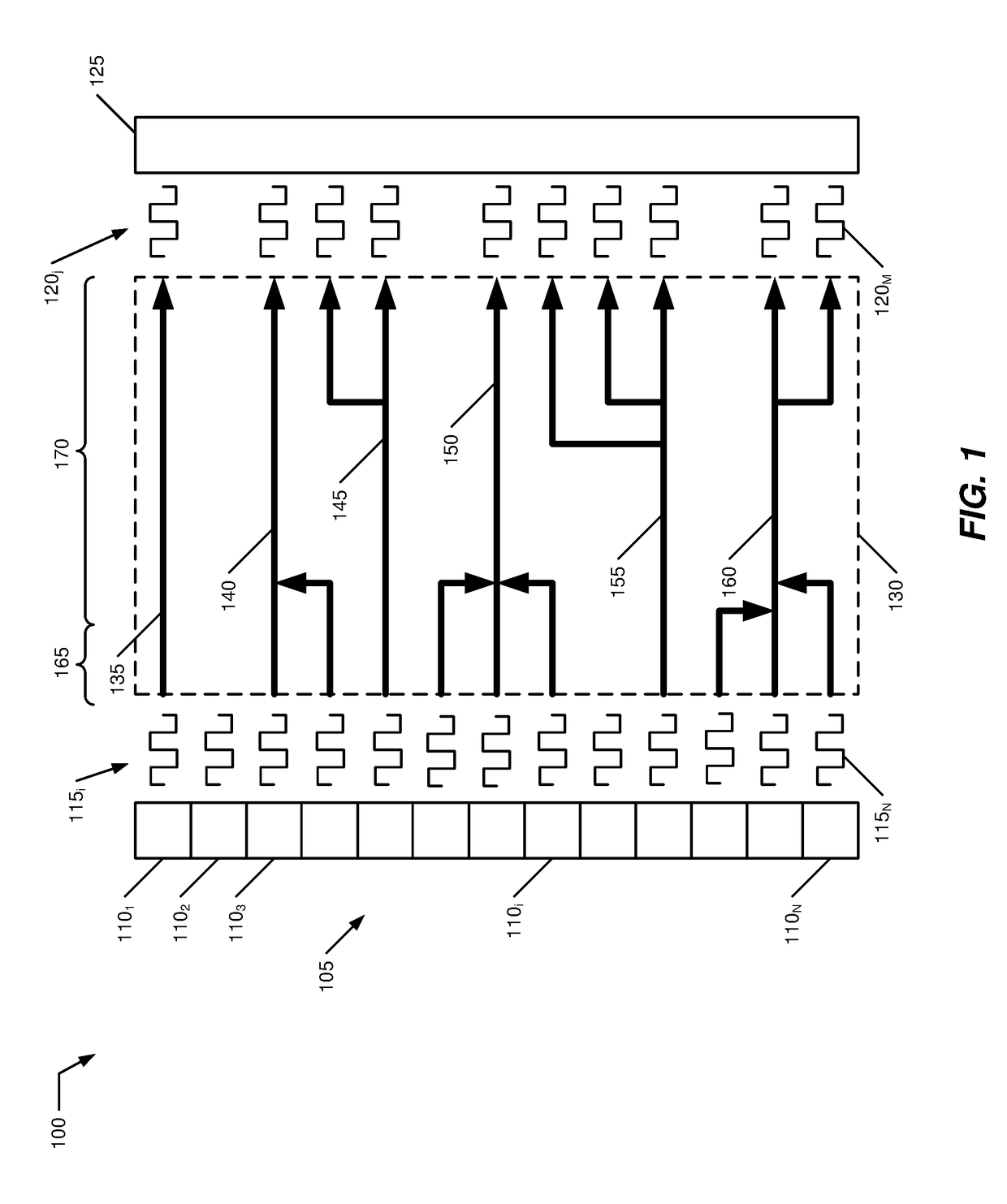
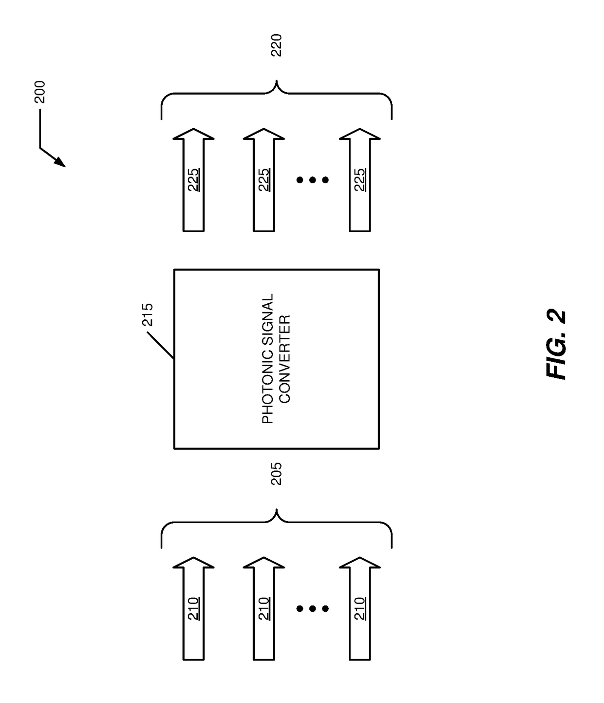
Digital projection free-space
optical beam-combining systems, which combine the outputs of high-resolution (2k or 4k) red, green and blue image engines (typically, images generated by DMD or LCoS SLM's are expensive achieving and maintaining these alignments are non-trivial.
In addition, these complex, multi-engine, multi-element optical combiner systems are not nearly as compact as is required for an HMD.
In addition, it is difficult to determine what the basic rationale is for two
image processing steps and calculation iterations, on two platforms, and why that is required to achieve the
smoothing and integration of the real and virtual wave-front inputs, implementing the proper
occlusion / opaquing of the combined scene elements.
It would appear that Gao's biggest concern and problem to be solved is the problem of the synthetic image competing, with difficulty, against the brightness with the
real image, and that the main task of the SLM thus seems to bring down, selectively, the brightness of portions of the real scene, or the real-scene overall.
And furthermore, when mobile, also moving, and also not known to the synthetic
image processing unit in advance.
Second, it is clear on inspection of the scheme that if any approach would, by virtue of the durability of such a
complex system with multiple, cumulative alignment tolerances, the accumulation of defects from original parts and wear-and-tear over time in the multi-element path, mis-alignment of the merged beam form the accumulated thermal and
mechanical vibration effects, and other complications arising from the complexity of a seven-element plus optical system, it is this system that inherently poses a probably degradation, especially over time, of the exterior live image wave-front.
Designing a system which must drive, from those calculations, two (and in a binocular system), four display-type devices, most likely of different types (and thus with differing color
gamut, frame-rate, etc.), adds complication to an already demanding system design parameter.
However, as higher resolution for HMD's is also desired, at the very least to achieve wider FOV, a recourse to a high-resolution DMD such as TI's 2k or 4k device means recourse to a very expensive solution, as DMD's with that feature size and number are known to have low yields, higher defect rates than can be typically tolerated for
mass-
consumer or business production and costs, a very high price point for systems in which they are employed now, such as digital cinema projectors marketed commercially by TI OEM's Barco, Christie, and NEC.
Night-time usage, to fully extend the usefulness of these display types, is clearly an extreme case of the low-light problem.
Thus, as we move past the most limited use-case conditions of the passive optical-see-through HMD type, as
information density increases—which will be expected as such systems become commercially-successful and normally-dense urban or suburban areas obtain tagging information from commercial businesses—and as usage parameters under bright and dim conditions add to the constraints, it is clear that “passive” optical see-through HMD's cannot escape, nor cope with, the problems and needs of any realistic practical implementation of mobile AR HMD.
Here, though, as has been established in the preceding in the discussions of the Gao disclosure, the limitations on increasing
display resolution and other system performance beyond 1080p / 2k, when employing a DLP DMD or other MEMS component are those of cost, manufacturing yield and defect rates, durability, and reliability in such systems.
In addition, limitations on image size / FOV from the limited expansion /
magnification factor of the planar optic elements (gratings structures, HOE or other), which expands the SLM image size but and interaction / strain on the human
visual system (HVS), especially the focal-system, present limitations on the safety and comfort of the viewer.
User response to the employment of similar-sized but lower resolution images in the Google Glass trial suggest that further straining the HVS with a higher-resolution, brighter but equally small
image area poses challenges to the HVS.
The demarcation was on
eye muscles used in ways they are not designed or used to for prolonged periods of time, and
proximate cause of this in the revised statement was the location of the small display image, forcing the user to look up.
However, the particular combination of eye-
muscle usage required for focal usage on a small portion of the real FOV cannot be assumed to be identical to that required for eye-motion across an entire real FOV.
The added complication is that the
level of detail in the constrained eye-motion domain may begin to rapidly, as resolution increases in scenes with complex, detailed motion, exceed the
eye fatigue from precision tool-work.
No rigorous treatment of this issue has been reported by any developers of optical view-through systems, and these issues, as well as eye-fatigue,
headaches, and dizziness problems that Steve Mann has reported over the years from using his
EyeTap systems, (which were reportedly in-part improved by moving the image to the center of the
field of view in the current Digital
EyeTap update but which have not be systematically studied, either), have received only limited comment focused on only a portion of the issues and problems of eye-strain that can develop from near-work and “
computer vision sickness.”
However, the limited public comment that Google has made available from Dr.
In addition, with respect to the existing limitations to VR HMD's, all such systems employing
OLED and LCD panels suffer from relatively low frame-rates, which contributes to motion
lag and latency, as well as negative physiological affects on some users, belonging in the
broad category of “simulator sickness.” It is noted as well that, in digital stereo-projection systems in cinemas, employing such commercially-available stereo systems as the RealD system, implemented for Texas Instruments DLP DMD-based projectors or Sony LCoS-based projectors, insufficiently
high frame rate has also been reported as a contributing to a fraction of the audience, as high as 10% in some studies, experiencing
headaches and related symptoms.
A further
impact on the performance of existing VR HMD's is due to the resolution limitations of existing
OLED and LCD panel displays, which in part contributes to the requirement of using 5-7″
diagonal displays and mounting them at a distance from the viewing
optics (and viewers eyes) to achieve a sufficient effective resolution), contributes to the bulk, size and balance of existing and planned offerings, significantly larger, bulkier, and heavier than most other optical headwear products.
But the expense of bringing to market, at sufficient volumes, requiring significant additional scale investments to fab capacity at acceptable yields, makes this prospect less practical for the near-term.
And it would only partially address the problem of bulk and size.
But these, too, have been limited by the core performance of the display technologies employed, in pattern following the limitations observed for
OLED, LCD and DMD-based reflective / deflective optical systems.
Even more fundamentally and universally in-common, they are also limited by the basic type of display / pixel technologies employed, as the frame-rate / refresh of existing core display technologies, whether fast LC, OLED or MEMS, and whether employing a mechanical scanning-
fiber input or other
optics systems disclosed for conveying the display image to the viewing
optics, all are still insufficient to meet the requirements of high-quality, easy-on-the-eyes (HVS), low power, high resolutions, high-
dynamic range and other display performance parameters which separately and together contribute to realizing
mass-market, high-quality enjoyable AR and VR.
To summarize the state of the prior art, with respect to the details covered in the preceding:“High-acuity” VR has improved in substantially in many respects, from FOV, latency, head / motion tracking, lighter-weight, size and bulk.But
frame rate / latency and resolution, and to a significant corollary degree, weight, size and bulk, are limited by the constraints of core display technologies available.And modern VR is restricted to stationary or highly-restricted and limited mobile use in small controlled spaces.VR based on an enclosed version of the optical view-through system, but configured as a
lateral projection-deflection system in which an SLM projects an image into the eye via a series of three optical elements, is limited in performance to the size of the reflected image, which is expanded but not much bigger than the output of the SLM (DLP DMD, other MEMS, or FeLCoS / LCoS), as compared to the total area of a standard eyeglass lens.
Eye-strain risks from extended viewing of what is an extremely-intense version of “close-up work” and the demands this will make on the
eye muscles is a further limitation on practical acceptance.
And SLM-type and size displays are also limit a practical path to improved resolution and overall performance by the scaling costs of higher resolution SLM's of the technologies referenced.Optical view-through systems generally suffer from the same potential for eye-strain by confinement of the eye-
muscle usage to a relatively small area, and requiring relatively small and frequent eye-tracking adjustments within those constraints, and for more than brief period of usage.
But users have reported eye-strain none-the-less, as has been widely document in the press by means of text and interviews from Google Glass Explorers.Optical view-through systems are limited in overlaid, semi-transparent
information density due to the need to organize tags with real-world objects in a perspective view.
The number of optical elements intervening in the
optical routing of the initial wave-front portion (also, a point to be added here, much smaller than the optical area of a conventional lens in a conventional pair of glasses), which is seven or close to that number, introduces both opportunities for image aberration, artifacts, and losses, but requires a
complex system of optical alignments in a field in which such complex free-space alignments of many elements are not common and when they are required, are expensive, hard to maintain, and not robust.
Nor is the problem of coordinating the
signal processing between 2-4 display-type devices (depending on
monocular of binocular system), including determination of the exactly what pixels from the real-field are the calibrated pixels for the proper synthetic ones, in a context in which preforming calculations to create proper relationships between real and synthetic elements in perspective view is already extremely demanding, especially when the individual is moving in an information-dense, topographically complex environment.
Mounted on a vehicle only compounds this problem further.
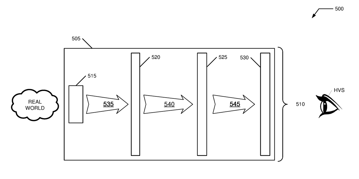
There are myriad additional problems for development of complete system, as compared to the task of building a optical set up as Gao proposes, or even of reducing it to a relatively compact-form factor.
Size, balance, and weight are just one of many consequences to the number and by implication, necessary location of the various processing and optics arrays units, but as compared to the other problems and limitations cited, they are by relatively minor, though serious for the practical deployment of such a system to field use, either for military or ruggedized industrial usage or
consumer usage.A 100% “indirect-view display” will have similar demands in key respects to the Gao proposal, with the exception of the number of display-type units and particulars of the alignment, optical system, pixel-system matching, and perspective problems, and thus throws into question the degree to which all key parameters of such a system should require “
brute force” calculations of the stored synthetic CG 3D mapped space in coordination with the real-time, individual perspective real-time view-through image.
The problem become greater to the extent that the calculations must all be performed, with the
video image captured by the forward video cameras, in the basic Barrilleaux and now possible Vrvana design, relayed to a non-local (to the HMD and / or t the wearer him / herself) processor for
compositing with the synthetic elements.

