Single-line-extracted pure rotational raman lidar to measure atmospheric temperature and aerosol profiles

Active Publication Date: 2018-07-05
WUHAN UNIV
View PDF0 Cites 11 Cited by
  • Summary
  • Abstract
  • Description
  • Claims
  • Application Information

AI Technical Summary

Benefits of technology

[0018]Each of the two Raman channels in our PRR lidar can exactly register the backscatter signal according to a single PRR line (J=6 or 16) and sufficiently suppress adjacent O2 molecule line signal as well as strong elastic signal. This allows the simple exact temperature dependence described by equation (2) to be applied in the temperature profile retrieval without introducing an assumed calibration function. The atmospheric temperature profile can be derived exactly from equation (2) after the constant parameters A and B are determined via comparison with accompanying local radiosondes (i.e., calibration). The constant B in equation (2) can also be figured out theoretically according to the difference of the rotational Raman energies for J=6 and 16. The consistency between the theoretical result and calibrated B value provides a test criterion for the validity of the single-line-extracted PRR lidar system. The aerosol backscatter and extinction profiles can be further determined strictly from one measured PRR line signal and elastic backscatter signal without additional assumptions (e.g. lidar ratio or Ångström relationship). The two obtained aerosol parameters as well as resultant lidar ratio can provide quantitati

Problems solved by technology

Although such routine radiosonde temperature profiles have a high accuracy and good altitude resolution, their low time resolution makes it unlikely to register some fast weather processes.
But, because the spectral extraction devices (interference filter or grating polychromator) utilized in the existing PRR lidars have a limited bandwidth, each rotational Raman channel has to extract several adjacent PRR lines of both N2 and O2 molecules rather than a single one

Method used


Image

  • Single-line-extracted pure rotational raman lidar to measure atmospheric temperature and aerosol profiles
  • Single-line-extracted pure rotational raman lidar to measure atmospheric temperature and aerosol profiles
  • Single-line-extracted pure rotational raman lidar to measure atmospheric temperature and aerosol profiles

Examples


Embodiment Construction

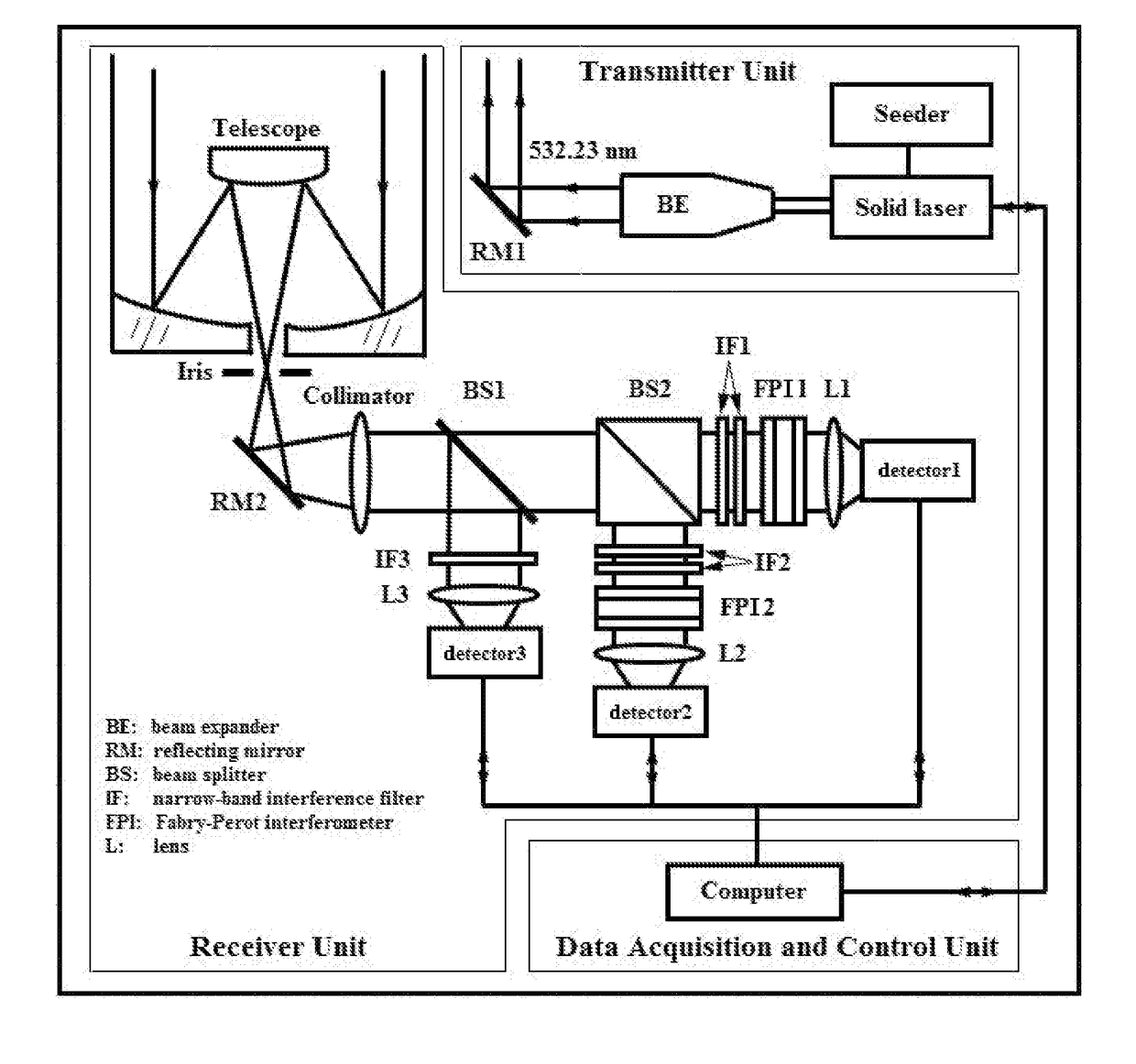
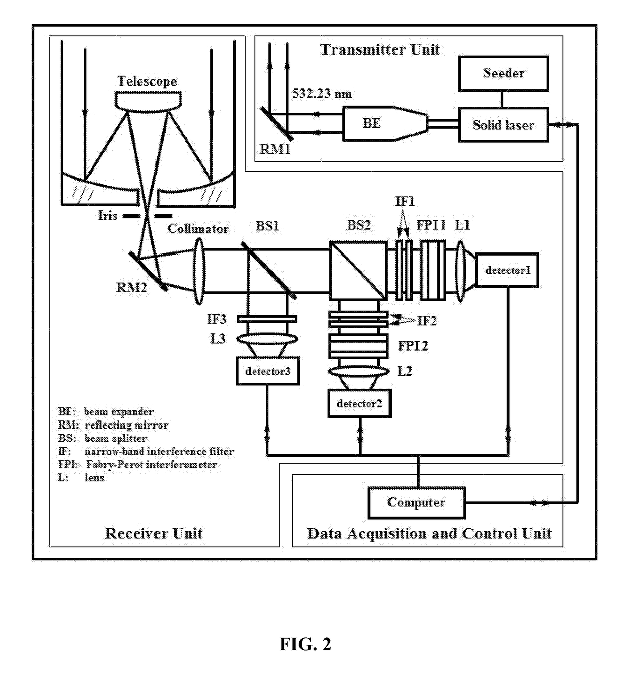
[0023]The invented lidar system comprises a transmitter unit, a receiver unit, and a data acquisition and control unit. FIG. 2 presents its schematic layout.

[0024]The transmitter unit comprises a seeder, a solid Nd: YAG laser, a beam expander (BE) and a first reflecting mirror (RM1). The seeder (NP Photonics Inc., US) generates an extremely narrow-band infrared 1064 nm fundamental laser light. The 1064-nm light is guided into the resonant cavity of the solid laser by an optical fiber. The solid laser (Powerlite 9030, Continuum, US) emits a 532.23-nm laser beam with a pulse energy of approximately 800 mJ, repetition rate of 30 Hz and linewidth of −1 (via a frequency doubling crystal). A home-made BE compresses the beam divergence by a factor of 8 and also reduces the radiant flux density of the output laser beam. The expanded laser beam is guided into atmosphere zenithward by the RM1 (reflectivity >99.5%) that is put on a two-dimensional electronically-adjustable mount (Kohzu, JP).

[0...


PUM


Abstract

A single-line-extracted pure rotational Raman lidar system, including: a transmitter unit configured to emit extremely narrow-band laser light that is guided into atmosphere zenithward; a receiver unit configured to collect backscattered signals from the atmosphere; and a data acquisition and control unit configured to deliver data and guarantee automatic operation of the lidar system orderly. The transmitter unit employs a powerful injection-seeded Nd: YAG laser to emit 532.23 nm laser beam with a pulse energy of approximately 800 mJ, a repetition rate of 30 Hz and linewidth of <0.006 cm−1. The lidar system has an optical bandwidth of approximately 30 pm for the two Raman channels and an optical bandwidth of 0.3 nm for an elastic channel, as well as a field of view of approximately 0.4 mrad. The two Raman channels extract the N2 anti-Stokes pure rotational Raman line signals with J=6 and 16, respectively.

Description

CROSS-REFERENCE TO RELATED APPLICATIONS[0001]Pursuant to 35 U.S.C. § 119 and the Paris Convention Treaty, this application claims the benefit of Chinese Patent Application No. 201710001666.2 filed Jan. 3, 2017, the contents of which are incorporated herein by reference. Inquiries from the public to applicants or assignees concerning this document or the related applications should be directed to: Matthias Scholl P.C., Attn.: Dr. Matthias Scholl Esq., 245 First Street, 18th Floor, and Cambridge, Mass. 02142.BACKGROUND OF THE INVENTIONField of the Invention[0002]The present disclosure of the invention belongs to the field of lidar remote sensing technique, and more particularly to simultaneous lidar measurements of atmospheric temperature and aerosol extinction and backscatter coefficients.Description of the Related Art[0003]Accurate and high-resolution measurements of atmospheric temperature are important for weather and climate monitoring. Vertical temperature profiles are acquired ...

Claims


Application Information

Patent Timeline
IPC IPC(8): G01S17/95G01K11/20G01S7/486G01S7/484G01S7/4861
CPCG01S17/95G01S7/484G01S7/4861G01K11/20Y02A90/10
Inventor YI, FANWENG, MIAOLIU, FUCHAOZHANG, YUNPENGYU, CHANGMINGHE, YUJINTAN, YINGYI, YANGPAN, XIANGLIANG
Owner WUHAN UNIV
Why Eureka
Try Eureka