Integrated LIDAR Illumination Power Control

Active Publication Date: 2018-10-04
VELODYNE LIDAR USA INC
View PDF0 Cites 25 Cited by
  • Summary
  • Abstract
  • Description
  • Claims
  • Application Information

AI Technical Summary

Benefits of technology

[0015]In one aspect, an illumination driver of a LIDAR measurement device is a GaN based integrated circuit (IC) that selectively couples an illumination source to a source of electrical power to generate a measurement pulse of illumination light in response to a pulse trigger signal. The GaN based illumination driver includes field effect transistors (FETs) that offer higher current density than conventional silicon based complementary metal oxide on silicon (CMOS) devices. As a result the GaN based illumination driver is able to deliver relatively large currents to an illumination source with significantly less power loss.
[0016]In a further aspect, a return pulse receiver IC receives a pulse command signal from a master controller and communicates the pulse trigger signal to the illumination driver IC in response to the pulse command signal. The pulse

Problems solved by technology

The number of pixels such devices can generate per unit time is inherently limited due limitations on the pulse repetition rate of a single laser.
Any alteration of the beam path, whether it is by mirror, prism, or actuation of the device that achieves a larger coverage area comes at a cost of decreased point cloud density.
This leads to opto-mechanical design complexity and alignment difficulty.
In addition, mechanical devices employed to scan the illumination beams in different directions may be sensitive to mechanical vibrations, inertial forces, and general environmental conditions.
Without proper design these mechanical devices may degrade leading to loss of performance or failure

Method used


Image

  • Integrated LIDAR Illumination Power Control
  • Integrated LIDAR Illumination Power Control
  • Integrated LIDAR Illumination Power Control

Examples


Example

[0040]Reference will now be made in detail to background examples and some embodiments of the invention, examples of which are illustrated in the accompanying drawings.

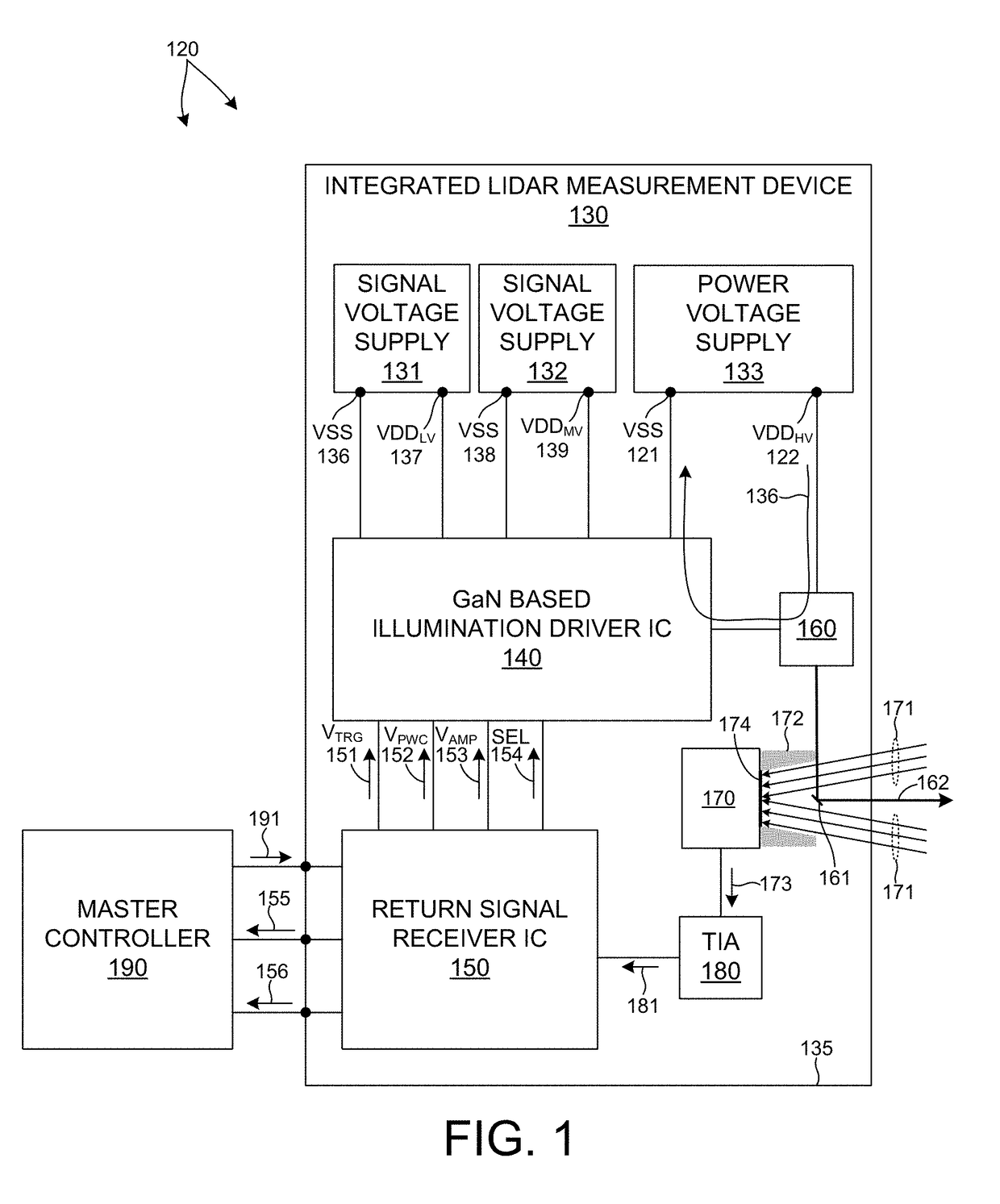
[0041]FIG. 1 depicts an LIDAR measurement system 120 in one embodiment. LIDAR measurement system 120 includes a master controller 190 and one or more integrated LIDAR measurement devices 130. An integrated LIDAR measurement device 130 includes a return signal receiver integrated circuit (IC), a Gallium Nitride based illumination driver integrated circuit (IC) 140, an illumination source 160, a photodetector 170, and a trans-impedance amplifier (TIA) 180. Each of these elements is mounted to a common substrate 135 (e.g., printed circuit board) that provides mechanical support and electrical connectivity among the elements.

[0042]In addition, in some embodiments, an integrated LIDAR measurement device includes one or more voltage supplies that provide voltage to the electronic elements mounted to substrate 135 and electr...


PUM


Abstract

Methods and systems for performing three dimensional LIDAR measurements with an integrated LIDAR measurement device are described herein. In one aspect, a Gallium Nitride (GaN) based illumination driver integrated circuit (IC), an illumination source, and a return signal receiver IC are mounted to a common substrate. The illumination driver IC provides a pulse of electrical power to the illumination source in response to a pulse trigger signal received from the return signal receiver IC. In another aspect, the GaN based illumination driver IC controls the amplitude, ramp rate, and duration of the pulse of electrical power based on command signals communicated from the return signal receiver IC to the illumination driver IC. In a further aspect, illumination driver IC reduces the amount of electrical power consumed by the illumination driver IC during periods of time when the illumination driver IC is not providing electrical power to the illumination source.

Description

CROSS REFERENCE TO RELATED APPLICATION[0001]The present application for patent claims priority under 35 U.S.C. § 119 from U.S. provisional patent application Ser. No. 62 / 480,119, entitled “Integrated LIDAR Illumination Power Control,” filed Mar. 31, 2017, the subject matter of which is incorporated herein by reference in its entirety.TECHNICAL FIELD[0002]The described embodiments relate to LIDAR based 3-D point cloud measuring systems.BACKGROUND INFORMATION[0003]LIDAR systems employ pulses of light to measure distance to an object based on the time of flight (TOF) of each pulse of light. A pulse of light emitted from a light source of a LIDAR system interacts with a distal object. A portion of the light reflects from the object and returns to a detector of the LIDAR system. Based on the time elapsed between emission of the pulse of light and detection of the returned pulse of light, a distance is estimated. In some examples, pulses of light are generated by a laser emitter. The ligh...

Claims


Application Information

Patent Timeline
IPC IPC(8): G01S7/484G01S7/481H01L29/20H01L27/06H01L23/528
CPCG01S7/484G01S7/4814H01L29/2003H01L27/0605H01L23/528H01L27/0629G01S17/42H05K1/181H05K2201/10151H05K2201/10166H05K2201/10121H05K2201/10022H05K2201/10015H05K2201/10106
Inventor HALL, DAVID S.LIOU, RAYMONDMILGROME, ORENDUMITREAN, MARIUS PAUL
Owner VELODYNE LIDAR USA INC
Why Eureka
Try Eureka