
Shutdown and non-shutdown separators for electrochemical devices

a separator and electrochemical technology, applied in the field of electrochemical devices, can solve the problems of destroying power generation capability, ineffective batteries, and elevated potential for battery failures and short circuits, and achieves good ionic conductivity, high mechanical strength, and thermal stability.

Active Publication Date: 2018-10-25
AVOMEEN ANALYTICAL SERVICES
View PDF3 Cites 6 Cited by
  • Summary
  • Abstract
  • Description
  • Claims
  • Application Information

AI Technical Summary

Benefits of technology

The present invention provides a solution for the production of shutdown and non-shutdown separators with improved mechanical strength, ionic conductivity, thermal stability, and better wettability. The solution involves a novel process using a reliable and cost-effective casting technique with specific polymers and fillers. The separators have improved air permeability, low electrical impedance, high thermal resistance, and enhanced holding capacity when used in electrochemical devices. Additionally, the separators have a uniform surface appearance and can be easily assembled. The invention also has lower material costs and can be mass-produced at relatively low costs.

Problems solved by technology

Any failure during use, specifically in terms of structural integrity permitting abnormally high amounts of current to pass or for the electrodes to touch, would destroy the power generation capability and render the battery totally ineffective.
Non-uniformity of electrolyte dispersion may result in dendritic formations within the cell and on the separator surface, thereby creating an elevated potential for battery failures and short circuiting therein.
However, in certain situations, elevated temperatures, either from external sources or within the cell itself, may expose susceptible separator materials to undesirable shrinking, warping, or melting, any of which may deleteriously affect the capability of the battery over time.
As such, since reduction of temperature levels and / or removal of such battery types from elevated temperatures during actual utilization are very difficult to achieve, the separator itself should include materials that can withstand such high temperatures without exhibiting any appreciable effects upon exposure.
To date, however, as noted above, the standards in place do not comport to such critical considerations.
Currently, such properties are not effectively provided in tandem to such a degree.
For instance, one manufacturer has disclosed and marketed an expanded film battery separator with very low pore size, which is very good in that respect, as noted above; however, the corresponding air resistance for such material is extremely high, thus limiting the overall effectiveness such a separator.
Additionally, the overall mechanical strengths exhibiting by these two materials are very limiting; the first separator has excellent strength in the machine direction, but nearly zero strength in the cross (transverse) direction.
Such low cross direction strength requires very delicate handling during manufacture, at least, as alluded to above.
However, the measured tensile strengths of the second separator are quite low in effect, thus relegating the user to carefully manipulation and placing such materials during manufacture as well.
Likewise, the dimensional stability of such prior battery separators are highly suspect due to these tensile strength issues, potentially leading to materials that undesirably lose their structural integrity over time when present within a rechargeable battery cell.
As such, although such a separator exhibiting low air resistance and low pore size, as well as high tensile strength overall and at relatively isotropic levels, proper chemical stability, structural integrity, and dimensional stability (particularly upon exposure to elevated temperatures), is highly desired, to date there has been a decided lack of provision of such a worthy separator material.
However, these polyolefin-based separators suffer from low porosity, poor electrolyte wettability, and severe thermal shrinkage at elevated temperature.
The poor electrolyte wettability impairs the rate capability and cycling stability of the battery, and brings a series of disadvantages in the manufacturing process.
The severe thermal shrinkage of polyolefin-based separators causes serious internal electrical short circuit, thus finally leading to fire disaster or explosion when the cells are exposed to abnormal conditions.

Method used


Image

  • Shutdown and non-shutdown separators for electrochemical devices
  • Shutdown and non-shutdown separators for electrochemical devices
  • Shutdown and non-shutdown separators for electrochemical devices

Examples


Embodiment Construction

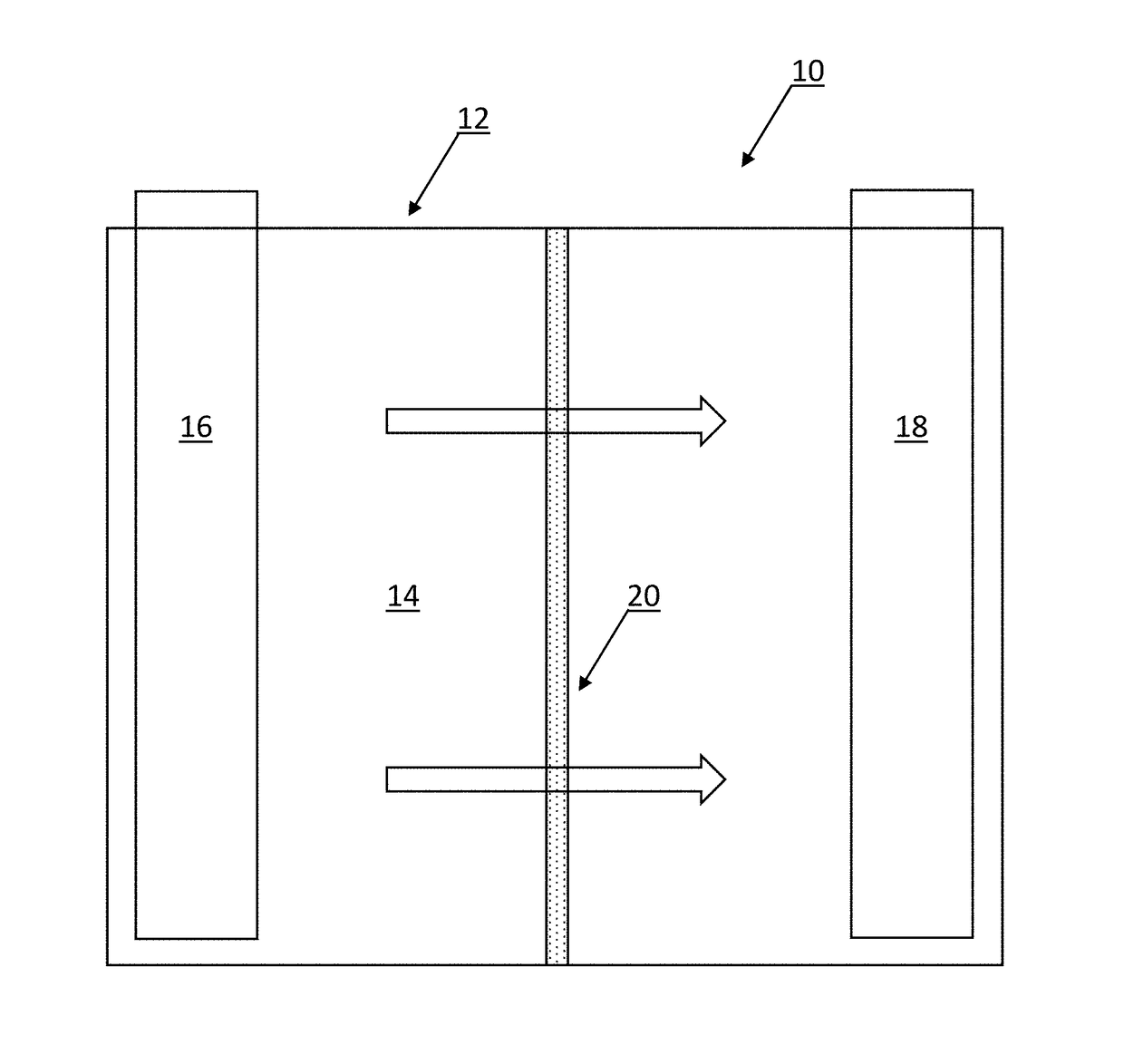
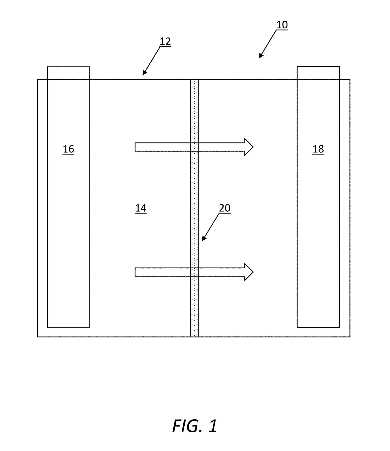
[0037]FIG. 1 is a schematic diagram illustrating one exemplary embodiment of a conventional electrochemical device (battery) utilizing the shutdown or non-shutdown separator of the present invention. In general, the battery 10 includes a housing 12 containing an electrolyte solution 14 enabling the transport of ions from an anode 16 to a cathode 18 through a separator 20, such as the shutdown or non-shutdown separator of the present invention, in the discharge of electrical current.

[0038]As described herein above, the present invention finds a solution to the problem plaguing the industry for many years to obtain shutdown and non-shutdown separators that have both high mechanical strength (machine and transverse direction), good ionic conductivity, thermal stability, high porosity, and better wettability. The solution is accomplished through a novel process that involves a reliable, robust, reproducible, and cost effective casting technique for a shutdown separator with, for example...


PUM

PropertyMeasurementUnit
temperatureaaaaaaaaaa

Abstract

The present invention provides a novel process that involves a reliable, robust, reproducible, and cost effective casting technique for a shutdown separator with, for example, a combination of poly(vinylidene fluoride-co-hexafluoropropylene) (PVdF-HFP) copolymer, polysulfonamide (PSA) / polyether imide (PEI), and CaCO3 powder, and for a non-shutdown separator with, for example, a combination of polysulfonamide (PSA) / polyether imide (PEI), filler / plasticizer, and metal oxide nanostructures (SiO2, TiO2, and Al2O3).

Description

FIELD OF THE INVENTION[0001]The present invention relates generally to electrochemical devices. More specifically, the present invention relates to shutdown and non-shutdown separators for electrochemical devices.BACKGROUND OF THE INVENTION[0002]Batteries have been utilized for many years as electrical power generators in remote locations, for example. Through the controlled movement of ions between electrodes (anode and cathode), a power circuit is generated, thereby providing a source of electricity that can be utilized until the excess ions in one electrode are depleted and no further electrical generation is possible. In more recent years, rechargeable batteries have been created to allow for longer lifetimes for such remote power sources, although through the need for connecting such batteries to other electrical sources for a certain period of time. All in all, however, the capability of reusing such a battery has led to greater potentials for use, particularly through laptop ...

Claims


Application Information

Patent Timeline
Patent Type & Authority Applications(United States)
IPC IPC(8): H01M2/16C08L27/16C08L81/10C08K3/00
CPCH01M2/1653H01M2/1646C08K3/013C08L81/10C08L27/16H01M50/446Y02E60/10C08L71/00C08L79/00C08L27/06C08K3/22C08L25/06
Inventor CHANNU, VENKATA S. REDDYTHANEDAR, SHRI
Owner AVOMEEN ANALYTICAL SERVICES
Learn More