Plasma accelerator with modulated thrust

a technology of plasma accelerator and modulated thrust, which is applied in the field of ion sources employed, can solve the problems of increasing the electric power consumption, and increasing the complexity of the electrical system, and achieves the effect of increasing the collisional ionization rate of electrons

Inactive Publication Date: 2018-10-25
AERNNOVA +1
View PDF0 Cites 14 Cited by
  • Summary
  • Abstract
  • Description
  • Claims
  • Application Information

AI Technical Summary

Benefits of technology

[0033]Therefore, the electrons from the active cathode that enter into the discharge chamber describe a complex motion. They are accelerated along the electric field lines between the passive cathode and the chamber walls and are also confined by multiple magnetic-mirror fields. This combined effect of electron confinement and acceleration greatly increases the collisional ionization rate of electrons with the neutral gas atoms and therefore the ion production rate.

Problems solved by technology

An important limiting factor is the depletion of propellant, essential for in-orbit maneuvers, which eventually might force early satellite retirement.
Gridded ion engines require a minimum of two active cathodes and therefore a number of power supplies that increase the complexity of the electrical system, as well as the electric power consumption.
Thermal control also becomes an issue because of the high operational temperatures of active cathodes, typically over 2000 K. Different thruster elements are heated up to high temperatures by the released infrared radiation.
Additionally, the high bias voltages required for ion beam acceleration, typically of a few kilovolts, also give rise to sparking and electric arcing between the grids, also subjected to both thermal stresses and charged particle bombardment.
All these factors reduce the lifetime of gridded ion engines.
This introduces oscillations in the deflection of the plasma beam exhaust in the direction perpendicular to the axis of symmetry of the thruster that are difficult to control and therefore the delivered thrust.

Method used


Image

  • Plasma accelerator with modulated thrust
  • Plasma accelerator with modulated thrust
  • Plasma accelerator with modulated thrust

Examples


Embodiment Construction

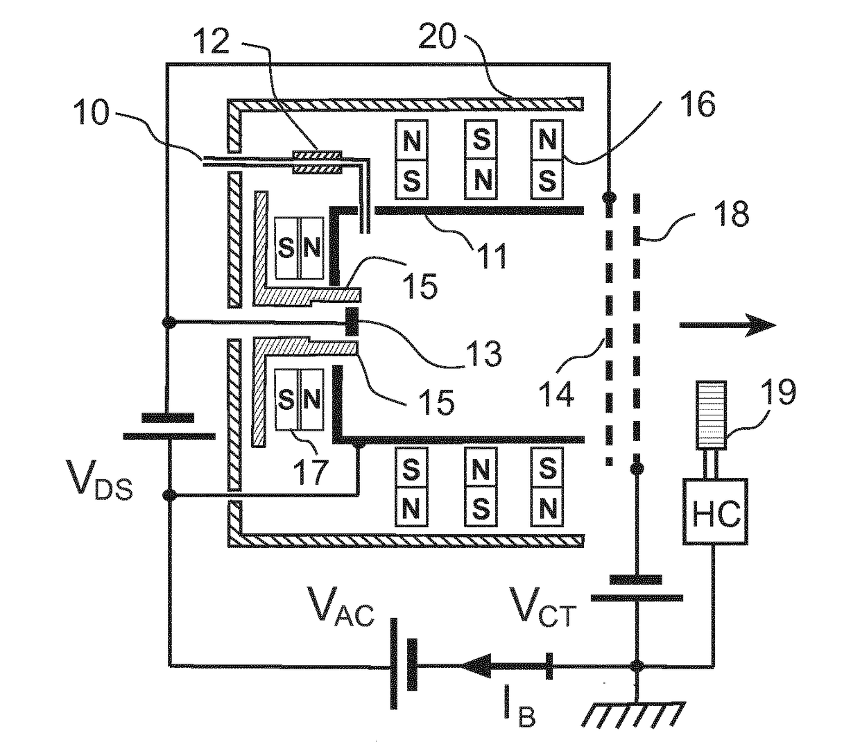
[0042]FIG. 1 shows the cross sectional plan scheme along the axial direction of symmetry of the present invention with its electrical connections. The neutral gas employed as propellant is introduced through the pipe 10, into the discharge chamber 11. The pipe 10 is electrically insulated from the controlled gas leak system by the ceramic connector 12.

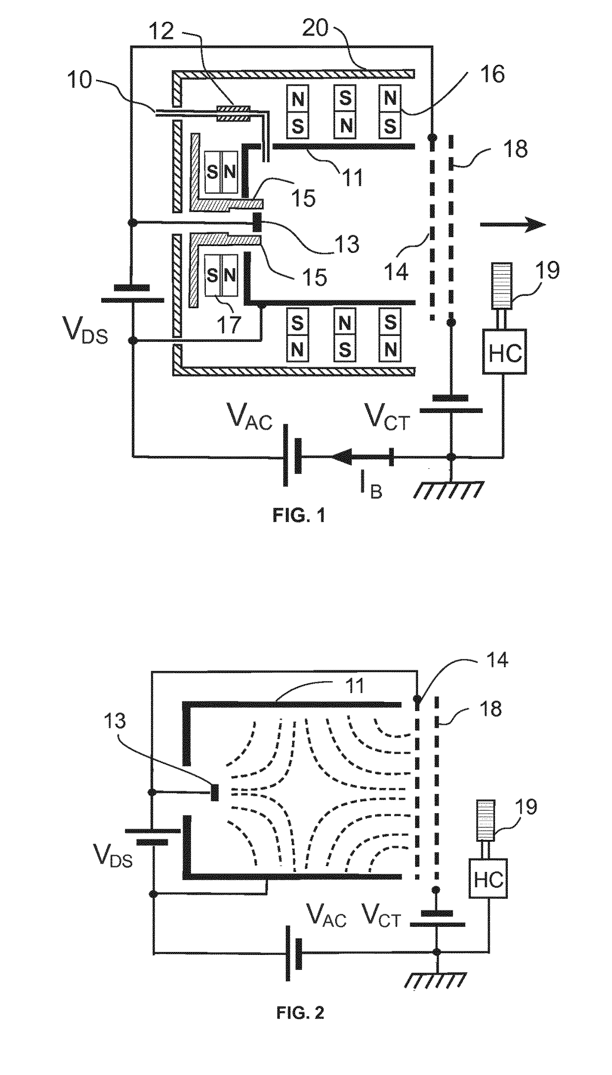
[0043]The plasma is essentially produced by the neutral gas atom collisional ionization by electrons from the active cathode 19 placed outside the discharge chamber 11. The electron source 19 can have different forms, such as a hollow cathode plasma discharge or thermionic electron emitter. This active cathode 19 provides electrons both along the direction of the control grid 18 and also in the opposite direction of the exiting ion beam indicated by the arrow in FIG. 1 for space charge neutralization. The block HC in FIGS. 1 and 2 represents control and heating and control system of the electron source 19.

[0044]A fraction of the electr...


PUM


Abstract

The invention relates to a plasma accelerator that produces and controls a plasma stream exhaust, in particular for space propulsion. The ions are produced inside the discharge chamber by working gas collisional ionization by electrons from a single electron source placed outside, also employed for ion beam neutralization. The ion motion is directed outwards through the exit side by the electric field between a cathode grid and the walls of the plasma chamber. The acceleration voltage imparts energy to the ion flux and an electrically biased control grid modulates the ion outflow from the discharge chamber and the electron inflow from the electron source. This allows electrical control of throttle and/or modulation of thrust delivered along the longitudinal direction of the thruster axis. Several plasma accelerators could be clustered together to provide controlled non-axial thrust using the individual control of throttle.

Description

FIELD OF THE INVENTION[0001]The present invention relates to ion sources employed as plasma thrusters for space propulsion and in-orbit corrections of space probes and satellites.BACKGROUND[0002]Ion thrusters and plasma accelerators produce high velocity streams of ions and electrons that impart momentum to spacecrafts. The propulsion of satellites using plasma streams is in increasing demand in order to improve the performances of satellites. An important limiting factor is the depletion of propellant, essential for in-orbit maneuvers, which eventually might force early satellite retirement. These orbit corrections and changes of orientation compensate the small variations produced in the periodic motion of satellites by the gravitational forces of the sun, the moon, as well as by the irregular distribution of the Earth's mass. Replacing the usual chemical rocket engines with plasma-based propulsive systems, characterized by high propellant exhaust speeds and large values of specif...

Claims


Application Information

Patent Timeline
Patent Type & Authority Applications(United States)
IPC IPC(8): H05H1/54F03H1/00H01J27/20H05H1/24
CPCH05H1/54F03H1/0018F03H1/0056H01J27/205H05H1/24
Inventor CASTILLO ACERO, MIGUEL ANGELCONDE LOPEZ, LUISDOMENECH GARRET, JUAN LUISDONOSO VARGAS, JOSE MANUELDEL RIO FERNADEZ, EZEQUIEL
Owner AERNNOVA
Why Eureka
Try Eureka