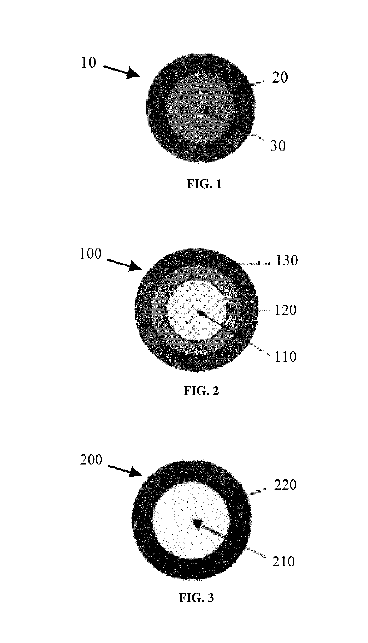
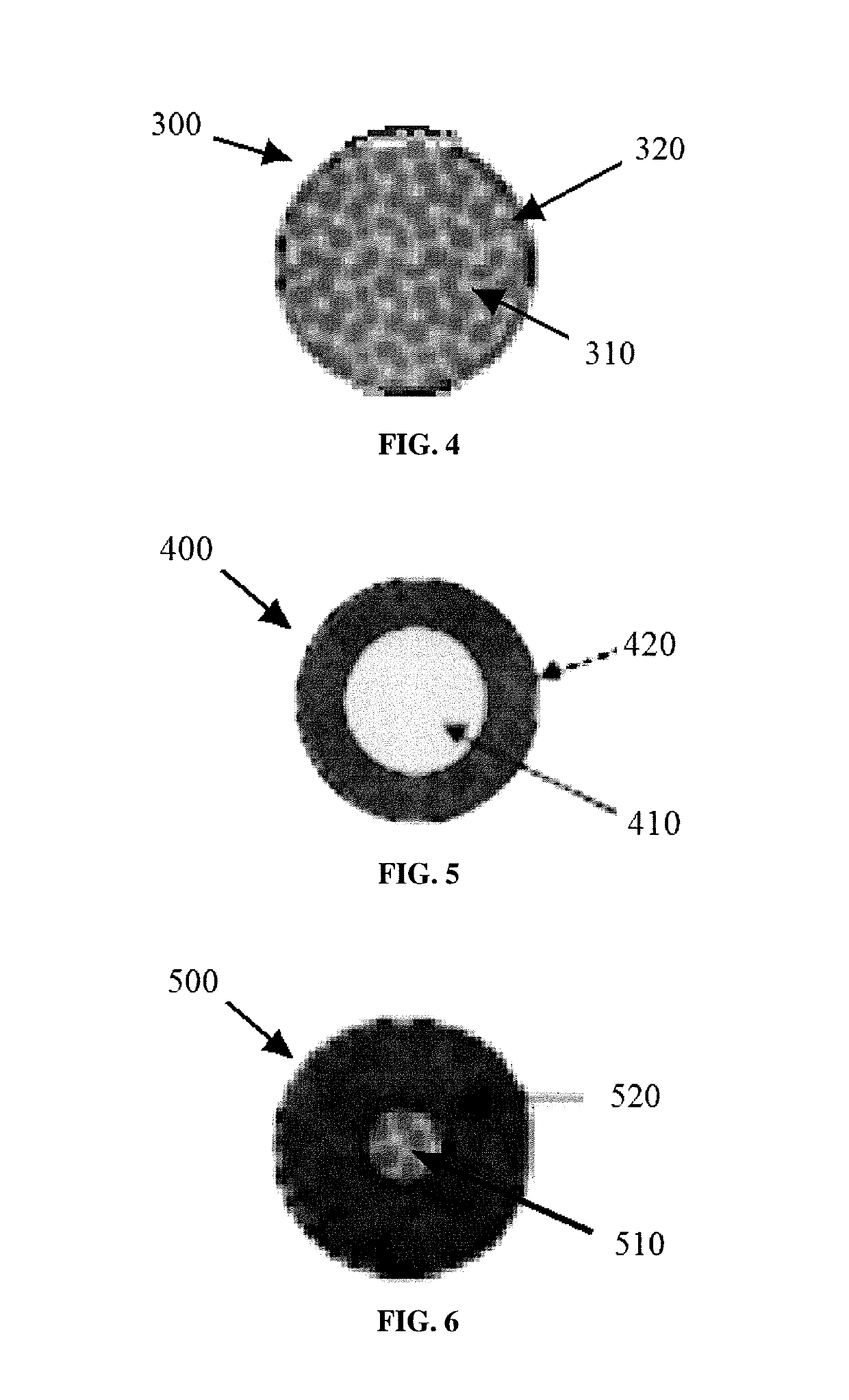
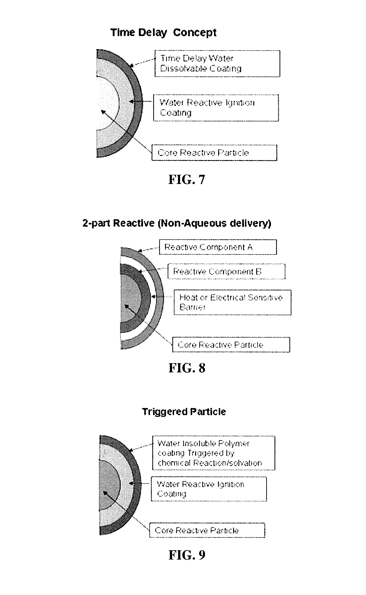
Material and Method of Controlled Energy Deposition

Active Publication Date: 2019-06-20
TERVES
View PDF0 Cites 6 Cited by
  • Summary
  • Abstract
  • Description
  • Claims
  • Application Information

AI Technical Summary

Benefits of technology

[0027]In one non-limiting embodiment of the present invention, there is the provision of a reactive composite that has been engineered to be a high strength reactive composite that is useful for oil and gas completions and well stimulation processes, enhanced oil and gas recovery operations, as well as in defensive and mining applications requiring high energy

Problems solved by technology

Well-known problems exist with use of conventional fracturing fluids in fracking operations.
For example, proppants including sand and other solid particulates degrade pumping components and piping over time, thereby reducing equipment lifetimes. Proppant particles can also constitute a high-volume fraction of the fracturing fluid that can adversely increase the density of the fracturing fluid.
Dense and heavy proppants can cause excessive loads on injection pumps and increase costs for pumping.
In addition, chemicals introduced in fracturing fluids can leach into aquifers and contaminate the ground water or deleteriously impact the environment where reservoirs are located.
Other types of chemicals can be potentially carcinogenic or can include explosives or other high-energy compounds that themselves are problematic or otherwise require extreme or careful handling.
Furthermore, fracturing fluids developed for oil/gas rec

Method used


Image

  • Material and Method of Controlled Energy Deposition
  • Material and Method of Controlled Energy Deposition
  • Material and Method of Controlled Energy Deposition

Examples


example 1

[0126]Magnesium alloy powder containing nickel, iron, carbon, copper, cobalt, galvanic activators and / or dopants and having a particle size distribution of 0.5-10 microns is compounded in a mixing extruder with PVA at a concentration of 60 vol. %. The material is extruded into strands having a cross-section of 300 microns and chopped into roughly equiaxed particles in circulating oil. The particles are further coated with 10 microns of PVA using the evaporation of PVA in isopropyl alcohol. The resultant reactive composite is reactive with brine to generate local gas formation and energy release after a 30 minute delay after 50° C. exposure.

example 2

[0127]Calcium metal is milled with PVA resin in isopropynol in a high energy mill. The isopropyl alcohol is evaporated and the PVA-coated fine calcium powder is mixed with additional PVA resin and extruded in a compounding extruder into 300 micron strands, which are chopped under oil into approximately equiaxed particles. A one-micron coating of PGA is added to the surface of the particles. The resultant particles react over a 10-15 minute period after a 5-minute delay in 55° C. brine.

example 3

[0128]Magnesium powder is dry-milled under inert atmosphere with about 10-60 vol. % of 1-3 microns carbonyl iron powder (a composite of iron and carbon) and a small amount of AlCl3 solid acid in isopropyl alcohol with PVA and stearic acid organic to produce a composite powder blend. The milled magnesium-iron-AlCl3—PVA blend is granulated to form 0.2-0.5 mm reactive beads. The beads react with water to form H2 and MgOH over a 3-20 minute period.


PUM


Abstract

A high strength engineered reactive composite that includes a reactive core. These reactive composites are useful for oil and gas completions and well stimulation processes, enhanced oil and gas recovery operations, as well as in defensive and mining applications requiring high energy density and good mechanical properties.

Description

[0001]The present invention claims priority on U.S. Provisional Patent Application Ser. No. 62 / 608,083 filed Dec. 20, 2017, which is incorporated herein.FIELD OF THE INVENTION[0002]The present invention relates to reactive composites that can be used to provide controlled generation of heat and / or pressure in situ to a wellbore, geologic formation, or other remote operations through interaction with water and / or some other or additional chemical present at the wellbore, geologic formation, or other remote operation location. The invention also relates to individual particles or agglomerates which have applied to their surface a second, discreet phase material having a different composition from the particle or agglomerate which 1) provides for at least partial control over the reaction with the core particle or agglomerate with the surrounding environment, and / or 2) may be tailored by controlling the relative particle sizes and / or amounts to provide a controlled reactivity rate. The...

Claims


Application Information

Patent Timeline
IPC IPC(8): E21B43/26C09K8/66
CPCE21B43/26C09K8/665C09K8/68C09K8/805C09K8/88C09K8/70
Inventor SHERMAN, ANDREW
Owner TERVES
Why Eureka
Try Eureka