
Filter medium, method for manufacturing same, and filter unit comprising same

a filter medium and filter unit technology, applied in the field of filter medium, can solve the problems of filter medium damage, filter medium deformation and damage, and achieve the effects of reducing the shape and structure of the filter medium, high flow rate, and reducing the damage of the filter medium

Active Publication Date: 2020-01-16
AMOGREENTECH CO LTD
View PDF0 Cites 5 Cited by
  • Summary
  • Abstract
  • Description
  • Claims
  • Application Information

AI Technical Summary

Benefits of technology

The present invention provides a filter medium that can minimize deformation and damage to its shape and structure during a water treatment operation. It also ensures a high flow rate and an extended use period due to its durability and water permeability. Additionally, it offers excellent chemical resistance, easy control of contamination, and excellent filtration performance with respect to contaminants that have positive ions such as a cationic compound. Furthermore, the filter medium includes a nanofiber web with silver, which provides an excellent antibacterial effect to disinfect bacteria in water. Additionally, its electrochemical adsorption performance allows it to effectively filter contaminants such as microbes, cationic compounds, viruses, etc.

Problems solved by technology

Here, there is a problem in which foreign substances which remain in the filter medium degrade filtration performance.
However, the high pressure applied while the filter medium is cleaned may cause damage of the filter medium, and a problem of delamination may occur in the case of a filter medium having a multilayer structure.
Generally, since most filter medium materials capable of being manufactured by electrospinning are hydrophobic, filter media manufactured using the same have excellent performance in chemical resistance, strength, and the like but have disadvantages such as low filtration performance and severe contamination.
In this case, there is a problem in which when a water-soluble polymer comes into contact with water, the polymer is easily detached from the hydrophobic filter medium such that hydrophilicity thereof is divested.
In this case, it is very difficult to adjust solubility and a residual state of the hydrophilic polymer materials such that filtration properties change or the hydrophilic polymer materials are gradually eluted as time passes.

Method used


Image

  • Filter medium, method for manufacturing same, and filter unit comprising same
  • Filter medium, method for manufacturing same, and filter unit comprising same
  • Filter medium, method for manufacturing same, and filter unit comprising same

Examples


example 1

[0269](1) Manufacturing of Hydrophilic Coating Composition

[0270]As a first solvent, a mixture solution was prepared by dissolving 10 g of polyvinyl alcohol (Kuraray Co., Ltd, PVA217) having 1,800 degrees of polymerization and 88% degrees of saponification as a hydrophilic polymer compound in 500 g of ultrapure water at a temperature of 80° C. for six hours using a magnetic bar, and a first solution was prepared by cooling the mixture solution at room temperature, mixing with 1.5 g of sulfosuccinic acid (Aldrich, SSA) as a first crosslinking agent, and dissolving at room temperature for twelve hours.

[0271]As a second solvent, a second solution was prepared by dissolving 10 g of poly(styrene sulfonic acid-co-maleic acid) in 500 g of ultrapure water as a second crosslinking agent at room temperature for six hours using a magnetic bar. Afterwards, a coating solution was prepared by mixing and dissolving the first solution and the second solution for twelve hours. Afterwards, a hydrophil...

experimental example

[0277]Each of filter media manufactured according to examples and comparative examples was embodied as a filter unit as shown in FIG. 5A, and the following properties were evaluated and shown in Tables 1 to 4.

[0278]1. Measurement of Relative Water Permeability

[0279]With respect to filter units embodied using the filter media manufactured according to the examples and comparative examples, water permeability per 0.5 m2 of an area of a specimen was measured by applying a driving pressure of 50 kPa, and then water permeability of each of filter media according to other examples and comparative examples was measured on the basis of water permeability of the filter medium of Example 1 as 100 as a reference.

[0280]2. Evaluation of Filtration Efficiency of Positive Ions

[0281]With respect to the filter units embodied using filter media manufactured according to the examples and comparative examples, filtration efficiency with respect to Na+ was measured through ion chromatography analysis.

[0...

example 19

[0288]First, to prepare a spinning solution, a mixture solution was prepared by dissolving 12 g of polyvinylidene fluoride (Arkema Co., Ltd, Kynar761), as a fiber-forming component, in 88 g of a mixed solvent, in which dimethylacetamide and acetone were mixed at a weight ratio of 70:30, at a temperature of 80° C. for six hours using a magnetic bar. The spinning solution was injected into a solution tank of an electrospinning device and was discharged at a speed of 15 μl / min / hole. Here, in a spinning section, a temperature of 30° C., a humidity of 50%, and 20 cm of a distance between a collector and a spinning nozzle tip were maintained. Afterwards, a fiber web formed of PVDF nanofibers was manufactured by applying a voltage of 40 kV or higher to a spinning nozzle pack using a high voltage generator simultaneously while applying an air pressure of 0.03 MPa per a nozzle of the spinning nozzle pack. Also, to form a hydrophilic coating layer on an outer surface of nanofibers, a first mi...


PUM

PropertyMeasurementUnit
degree of polymerizationaaaaaaaaaa
porosityaaaaaaaaaa
pore diameteraaaaaaaaaa

Abstract

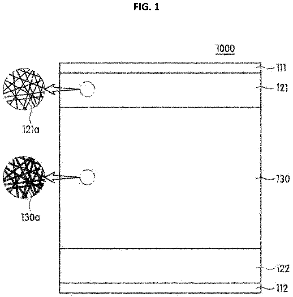
A filter medium according to one embodiment of the present invention comprises: a first support having a plurality of pores; a nanofiber web comprising nanofibers disposed on upper and lower portions of the first support and forming a three-dimensional network structure, and a hydrophilic coating layer formed on at least a part of an outer surface of the nanofibers, wherein the hydrophilic coating layer is formed of a hydrophilic coating composition comprising a hydrophilic polymer compound having at least one functional group selected from a hydroxyl group and a carboxyl group and a crosslinking agent comprising at least one sulfone group; and a second support having a plurality of pores interposed between the first support and the nanofiber web.

Description

TECHNICAL FIELD[0001]The present invention relates to a filter medium, and more particularly, to a filter medium, a method of manufacturing the same, and a filter unit including the same.BACKGROUND ART[0002]Separation membranes may be classified, according to pore sizes thereof, into a microfilter (MF) membrane, an ultrafiltration (UF) membrane, a nanofiltration (NF) membrane, and a reverse osmosis (RO) membrane.[0003]Although the above separation membranes have differences in a purpose and a pore size thereof, they are filter media formed of fiber, porous polymer filter media, or have the form of a composite membrane in common.[0004]Meanwhile, some of a variety of foreign substances included in water to be treated may remain in pores of a filter medium on which water treatment is repetitively performed, or an attached layer may be formed on a surface of the filter medium. Here, there is a problem in which foreign substances which remain in the filter medium degrade filtration perfo...

Claims


Application Information

Patent Timeline
Patent Type & Authority Applications(United States)
IPC IPC(8): B01D65/08B01D63/08B01D65/02B01D69/06B01D67/00C02F1/44B01D69/02B32B5/02B32B5/26B32B37/18B32B37/02
CPCB01D71/32B01D2323/02B01D63/08B32B2327/12B32B5/26B32B2255/26B32B2255/02B32B2329/04C02F1/44B01D2325/02B32B5/022B01D69/02B32B2307/728B32B2323/10B32B37/02B32B2262/0238B01D67/0002B32B37/182B01D65/02B01D2325/36B32B2262/12B32B2307/726B32B2323/04B01D2321/04B32B2262/0253B01D67/0088B32B2305/20B01D69/06B01D65/08B01D39/16B01D39/20C02F1/442B01D67/002B01D2323/39B01D2323/30B01D67/0093B32B37/24B32B2037/243B32B2307/546B32B2262/0276B32B2255/205B32B2262/0292B32B2307/714B32B2262/062B32B2307/306B32B2262/0223B32B2262/0261B32B5/08B32B2255/28B32B2250/20B32B2307/718B32B5/026B32B2307/732B32B2307/73B32B5/024B32B2250/05B32B7/02B32B2307/748B32B2260/046B32B2307/7145B32B2260/023B01D67/00042B01D2325/0283
Inventor SEO, IN YONGJEONG, UI YOUNG
Owner AMOGREENTECH CO LTD
Learn More