
Negative electrode for non-aqueous electrolyte secondary battery and non-aqueous electrolyte secondary battery using the same

a secondary battery and non-aqueous electrolyte technology, applied in the direction of active material electrodes, cell components, electrical apparatus, etc., can solve the problems of high charge and discharge capacity, sub>, difficult to obtain capacity and energy density, etc., and achieve the effect of increasing the discharge capacity and still maintaining the cycle li

Active Publication Date: 2020-01-16
NISSAN MOTOR CO LTD
View PDF4 Cites 1 Cited by
  • Summary
  • Abstract
  • Description
  • Claims
  • Application Information

AI Technical Summary

Benefits of technology

The invention provides a negative electrode for a non-aqueous electrolyte secondary battery that can be produced without heat treatment at high temperatures and increase the discharge capacity and cycle lifetime.

Problems solved by technology

However, in a carbon / graphite-based negative electrode material, since charging and discharging is achieved by intercalation and deintercalation of lithium ions in graphite crystals, there is a defect that a charge and discharge capacity higher than or equal to 372 mAh / g, which is the theoretical capacity obtainable from the maximum lithium intercalation compound LiC6, cannot be obtained.
Therefore, it is difficult to obtain a capacity and an energy density that satisfy a level for practical application in the use of vehicles having a cruising distance equivalent to that of gasoline vehicles, with a carbon / graphite-based negative electrode material.
However, a lithium ion secondary battery that uses a material capable of alloying with Li for the negative electrode undergoes large expansion and contraction in the negative electrode during charging and discharging.
Therefore, there is a problem that the cycle lifetime of the electrode is reduced.
Furthermore, in the case of a Si negative electrode active material, the capacity and the cycle durability are in a trade-off relationship, and there is a problem that it is difficult to enhance the cycle durability while exhibiting high capacity.

Method used


Image

  • Negative electrode for non-aqueous electrolyte secondary battery and non-aqueous electrolyte secondary battery using the same
  • Negative electrode for non-aqueous electrolyte secondary battery and non-aqueous electrolyte secondary battery using the same
  • Negative electrode for non-aqueous electrolyte secondary battery and non-aqueous electrolyte secondary battery using the same

Examples


examples

[0167]Hereinafter, the present invention will be described in more detail by way of Examples. However, the technical scope of the present invention is not intended to be limited only to the following Examples. Meanwhile, unless particularly stated otherwise, the unit “parts” means “parts by mass”. Furthermore, the processes up to the production of a non-aqueous electrolyte secondary battery were all carried out in a dry room.

production example

Binder Production Example 1

[0168]In a personal synthesis apparatus (manufactured by EYELA Rikakikai Co., Ltd., ChemiStation) of a 100-mL test tube container equipped with a stirrer, a temperature sensor, a nitrogen line, a vacuum line, and a reflux adaptor, 1.0 g of a methacryl-modified butadiene rubber (manufactured by Kuraray Co., Ltd., L-1253, number average molecular weight 7,000 (value obtained by GPC and calculated relative to polystyrene standards), having a methacryloyl group at a single terminal), 7.0 g of acrylic acid, 14 g of toluene, and 14 g of DMF were introduced, and a monomer mixture solution was prepared. Next, while the monomer mixture solution thus prepared was stirred at a stirring speed of 400 rpm, nitrogen was blown for one minute, and then a pressure reduction operation was performed for one minute. This operation was repeated five times to accomplish nitrogen purging. Subsequently, the monomer mixture solution was heated to 65° C., and an initiator mixture so...

example 1

[0188]As a liquid electrolyte, a solution was prepared by dissolving a lithium salt (LiPF6) in a solvent (an equivolume mixture of ethylene carbonate (EC) and diethyl carbonate (DEC)) at a concentration of 1 mol / L, and further dissolving fluoroethylene carbonate (FEC) at a concentration of 5% by mass in 100% by mass of the solution.

[0189]On the other hand, 100 parts by mass of the negative electrode material (1) prepared in the Negative Electrode Material Production Example 1 described above, 1 part by mass of acetylene black as a conductive aid, and 10 parts by mass (in terms of solid content) of the binder solution (1) produced as described above were weighed and dispersed in the above-mentioned solvent, and thus, a slurry for negative electrode active material layer was prepared.

[0190]On the other hand, a copper foil (thickness: 20 μm) was prepared as a negative electrode current collector. Then, the slurry for negative electrode active material layer prepared as described above ...


PUM


Abstract

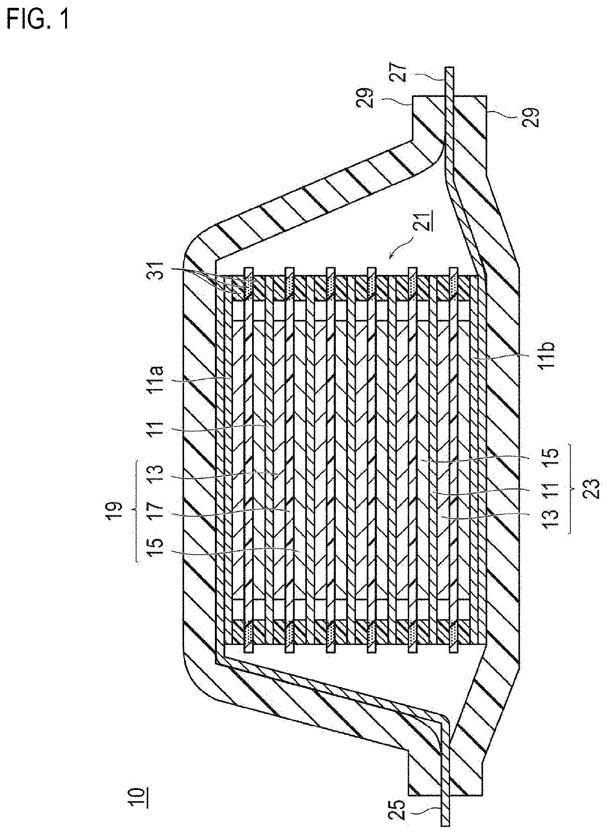
To provide a negative electrode for a non-aqueous electrolyte secondary battery that can be produced even without performing a heat treatment at a high temperature such as 2,000° C. or higher and can have the discharge capacity and the cycle characteristics (capacity retention) further increased.The negative electrode for a non-aqueous electrolyte secondary battery according to the invention has a configuration in which a negative electrode active material layer containing a negative electrode material and a binder is formed on the surface of a current collector. Further, the negative electrode material has a core portion including carbonaceous negative electrode active material particles; and a shell portion including a polyimide and silicon-based negative electrode active material particles and / or tin-based negative electrode active material particles. Here, there is a feature that the content of the silicon-based negative electrode active material particles and / or tin-based negative electrode active material particles with respect to 100% by mass of the content of the carbonaceous negative electrode active material particles is 2% to 20% by mass. Furthermore, there is a feature that the binder is formed of a hydrophilic unit and a hydrophobic unit bonded together.

Description

TECHNICAL FIELD[0001]The present invention relates to a negative electrode for a non-aqueous electrolyte secondary battery and a non-aqueous electrolyte secondary battery using the same.BACKGROUND ART[0002]In recent years, in order to cope with air pollution and global warming, reduction in carbon dioxide emission is strongly desired. In the automotive industry, there are growing expectations for a reduction in carbon dioxide emissions brought by introduction of electric vehicles (EV) or hybrid electric vehicles (HEV), and development of non-aqueous electrolyte secondary batteries such as secondary batteries for motor driving, which hold the key to the practical application of these vehicles, is being actively carried out.[0003]As a secondary battery for motor driving, the battery is required to have extremely high output characteristics and high energy as compared to lithium ion secondary batteries for consumer use, which are used for mobile telephones, notebook computers, and the ...

Claims


Application Information

Patent Timeline
IPC IPC(8): H01M4/133H01M4/587H01M4/38H01M4/36H01M4/62H01M4/134H01M10/0525
CPCH01M4/587H01M4/134H01M2004/027H01M4/133H01M4/622H01M4/366H01M10/0525H01M4/387H01M4/386H01M2004/021H01M4/1393H01M4/1395H01M4/625Y02E60/10
Inventor OHSAWA, YASUHIKOKUSACHI, YUKISATOU, HAJIMEAKAMA, HIROSHIHORIE, HIDEAKINISHIMURA, HIDEKI
Owner NISSAN MOTOR CO LTD
Learn More