Fuel cell system having oxygen sensor, and control method thereof

a fuel cell and oxygen sensor technology, applied in the direction of battery/fuel cell control arrangement, cell components, propulsion by batteries/cells, etc., can solve the problems of increasing voltage loss, fuel cell performance deterioration, and flooding, so as to reduce the irreversible deterioration of the fuel cell, prevent deterioration, and prevent deterioration

Active Publication Date: 2020-03-19
HYUNDAI MOTOR CO LTD +1
View PDF5 Cites 2 Cited by
  • Summary
  • Abstract
  • Description
  • Claims
  • Application Information

AI Technical Summary

Benefits of technology

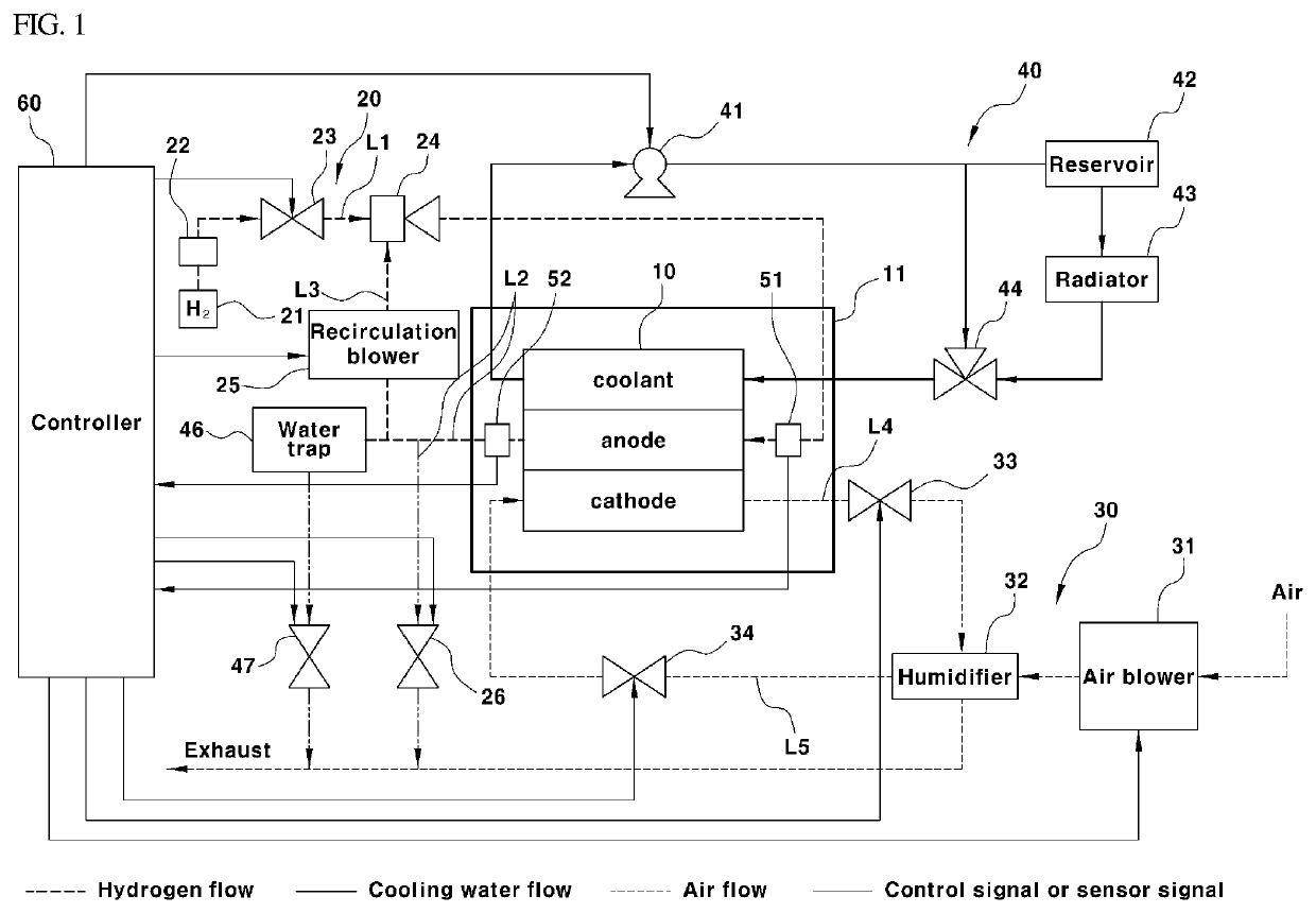
[0022]During operation of the fuel cell system, the controller may be configured to determine whether a current oxygen concentration on the anode side satisfies a predetermined condition that is predicted to generate a reverse voltage, based on a real time oxygen concentration value detected by the oxygen sensor and a first oxygen concentration reference value corresponding to the current fuel cell operating current. When the current oxygen concentration on the anode side is determined to satisfy the predetermined condition, the controller may be configured to operate the fuel cell operation device to reduce the oxygen concentration on the anode side to thus prevent deterioration on the anode side due to generation of the reverse voltage in the cells of the stack.
[0023]According to another aspect of the present invention, a method of controlling a fuel cell system may include: detecting an oxygen concentration in gases on an anode side by an oxygen sensor installed within a fuel cell stack during operation of the fuel cell system; determining, by the controller, whether a current oxygen concentration on the anode side satisfies a predetermined condition that is predicted to generate a reverse voltage, based on a real time oxygen concentration value detected by the oxygen sensor and a first oxygen concentration reference value corresponding to the current fuel cell operating current. When the current oxygen concentration on the anode side is determined to satisfy the predetermined condition, the method may include operating a fuel cell operation device to reduce the oxygen concentration on the anode side to thus prevent d

Problems solved by technology

However, when the water is excessively produced, flooding may occur, which is a water overflow phenomenon at high current density unless properly removed.
In the event of a flooding phenomenon, the excessive amount of water interferes with the efficient supply of the reaction gases into the fuel cell, thereby further increasing the voltage loss.
Additionally, the cell performance of the fuel cell may be deteriorated.
Further, when the R value decreases (R≤R1), the cell voltage deviation is extreme, leading to the vehicle being stopped.
Meanwhile, although the conventional control logic is applicable to the case where the cell performance may be reversibly recovered, it has a limit in an irreversible deterioration mode, such as a flooding phenomenon, in which the cell performance is degraded due to the accumulation or collection of water in the fuel cell stack, which causes interruption of the flow of reaction gases (hydrogen and air).
In addition, it is known that the reverse voltage generated in the cells in the fuel cell has a substantial adverse effect on the performance of the fuel cell, thereby substantially reducing the cell voltage.
The hydrogen shortage phenomenon often occurs in operating conditions such as uneven supply and distribution of hydrogen gas, a sudden increase in the load demand for the fuel cell, start-up of the fuel cell, etc.
When the reverse voltage state in the cell continues and an excessive reverse voltage state in which the cell voltage is less than about −2 V is reached, the heat generation of the fuel cell becomes excessive and thus, the membrane electrode assembly (MEA), the gas diffusion layer (GDL), and the like are generally

Method used


Image

  • Fuel cell system having oxygen sensor, and control method thereof
  • Fuel cell system having oxygen sensor, and control method thereof
  • Fuel cell system having oxygen sensor, and control method thereof

Examples


Embodiment Construction

[0035]It is understood that the term “vehicle” or “vehicular” or other similar term as used herein is inclusive of motor vehicles in general such as passenger automobiles including sports utility vehicles (SUV), buses, trucks, various commercial vehicles, watercraft including a variety of boats and ships, aircraft, and the like, and includes hybrid vehicles, electric vehicles, plug-in hybrid electric vehicles, hydrogen-powered vehicles and other alternative fuel vehicles (e.g. fuels derived from resources other than petroleum). As referral to herein, a hybrid vehicle is a vehicle that has two or more sources of power, for example both gasoline-powered and electric-powered vehicles.

[0036]Although exemplary embodiment is described as using a plurality of units to perform the exemplary process, it is understood that the exemplary processes may also be performed by one or plurality of modules. Additionally, it is understood that the term controller / control unit refers to a hardware devi...


PUM


Abstract

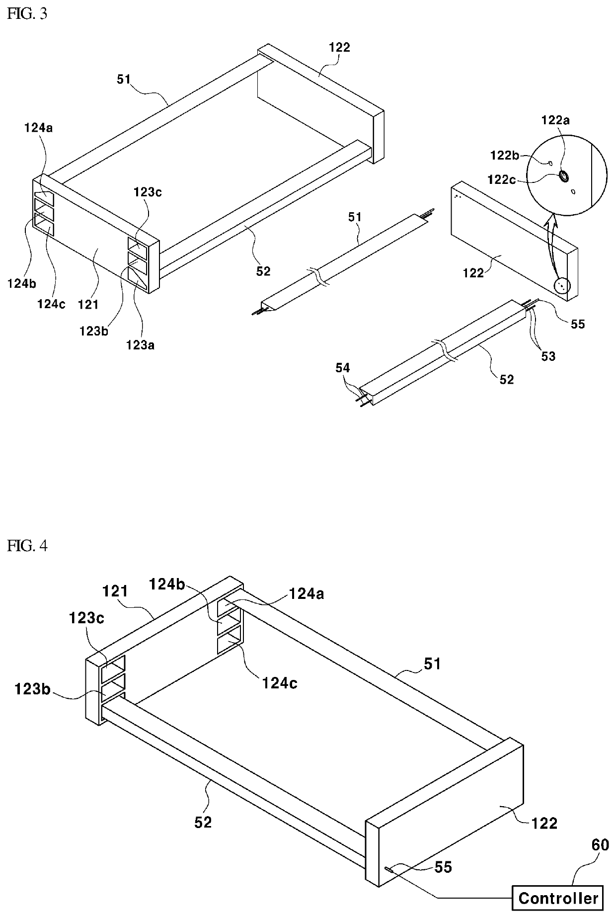
A fuel cell system and a control method thereof are provided. In the system, an oxygen sensor is mounted on the anode inlet side and the anode outlet side of a fuel cell stack to measure an oxygen concentration. Based on the measured oxygen concentration, a control operation is performed on the fuel cell system to reduce the oxygen concentration on the anode side. Accordingly, the irreversible deterioration of the fuel cell occurring due to the reverse voltage of the cell during driving of the fuel cell vehicle and the cathode carbon corrosion occurring due to the inflow of air during parking are effectively reduced, thereby increasing the durability of the fuel cell and the fuel cell vehicle.

Description

CROSS REFERENCE TO RELATED APPLICATION[0001]The present application claims priority to Korean Patent Application No. 10-2018-0111182, filed on Sep. 18, 2018, the entire contents of which is incorporated herein for all purposes by this reference.BACKGROUNDField of the Invention[0002]The present invention relates to a fuel cell system and a control method thereof and, more particularly, to a fuel cell system that enables normal driving of a vehicle even in an irreversible deterioration mode of the fuel cell due to the reverse voltage, and also responds to the irreversible deterioration due to the inflow of external air (oxygen) into a cathode during vehicle parking and the movement of the air to an anode, thereby improving the durability of the fuel cell and the vehicle, and a control method thereof.Description of the Related Art[0003]Generally, fuel cells are a type of power generation device that converts chemical energy of a fuel into electric energy by electrochemically reacting a...

Claims


Application Information

Patent Timeline
IPC IPC(8): H01M8/04791H01M8/1004H01M8/04223H01M8/0444H01M4/88
CPCH01M2250/20H01M8/04223H01M4/8807H01M8/04455H01M8/1004H01M8/04798H01M8/0444H01M8/04462H01M8/04791H01M8/04805B60L50/72B60L58/33H01M8/04089H01M8/04201H01M8/04231H01M8/0432H01M8/04447H01M8/04679H01M8/04753H01M8/043Y02E60/50Y02T90/40H01M8/04992
Inventor YU, JUNG HANOH, JONG KILPARK, GUN HYUNGHONG, BO KI
Owner HYUNDAI MOTOR CO LTD
Why Eureka
Try Eureka