
Electrode protective layer polymer and secondary battery to which same is applied

Active Publication Date: 2021-03-25
LG ENERGY SOLUTION LTD
View PDF0 Cites 0 Cited by
  • Summary
  • Abstract
  • Description
  • Claims
  • Application Information

AI Technical Summary

Benefits of technology

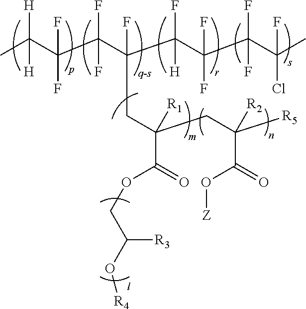
The present invention provides a polymer for an electrode protective layer that improves lithium ion conductivity and voltage stability of a secondary battery. The polymer includes a fluorine-based polymer with high lithium ion dissociation and a monomer unit comprising poly(alkylene oxide) and a thermocurable or photocurable functional group. The polymer is used as a protective layer for an electrode active material layer and does not inhibit lithium ion flow. It also has high chemical resistance for an electrolyte liquid, resulting in excellent performance of a secondary battery.

Problems solved by technology

A metal lithium negative electrode has received much attention with very high theoretical specific capacity of 3860 mAh / g and lowest electrochemical potential of −3.04 V (vs. standard hydrogen electrode), however, commercialization thereof has been delayed due to problems such as side reactions with an electrolyte liquid or non-uniform deposition / elution of lithium.
The SEI layer continues to undergo destruction and regeneration while a charge and discharge cycle of a battery is repeated, and a newly exposed lithium metal surface reacts again with an electrolyte liquid to induce a decrease in the Coulombic efficiency and a short-circuit through lithium dendrite growth in the battery, which delays commercialization of a secondary battery using a metal lithium electrode.
However, a phenomenon of reduced electrode protective effect was still observed after continuous battery driving, and this has been analyzed to be due to low lithium ion conductivity of an electrode, low flexibility, and crack occurrences caused by a non-uniform coating film.

Method used


Image

  • Electrode protective layer polymer and secondary battery to which same is applied
  • Electrode protective layer polymer and secondary battery to which same is applied
  • Electrode protective layer polymer and secondary battery to which same is applied

Examples


preparation example (

2-3) Preparation of Grafting Copolymerized PVDF-co-(PCTFE-g-P(mPEGMA-co-(HEMA-AOI)))-co-PTrFE (A2-3)

[0192]In a 1000 ml flask, 15 g of P(VDF-co-CTFE-co-TrFE) having a weight average molecular weight (Mw) of 560,000 as a fluorine-based polymer, and 116 g of mPEGMA (ethylene oxide repeating number=9), and 0.70 g of HEMA, as monomers to polymerize, were introduced to 350 ml of a dimethylformamide (DMF) solvent, and were stirred for 1 hour under the nitrogen condition.

[0193]After that, 0.003 g of CuCl2 as an ATRP reaction catalyst, 0.014 g of TPMA as a ligand, and 0.04 g of AIBN as a reducing agent were introduced to the flask, and the ATRP reaction was proceeded for 30 hours at 60° C. under the nitrogen condition with stirring. Herein, the monomer conversion rate was 80%.

[0194]After the polymerization was completed, the reaction material was cooled to room temperature, and air was bubbled into the reaction vessel for 2 hours. 0.0004 g of 2,6-bis(1,1-dimethylethyl)-4-methylphenol (BHT) w...

examples 1-1 to 1-5

Preparation of Cured Electrode Protective Layer

[0198]Each of the fluorine-based graft polymers prepared in Preparation Examples 1-1 to 1-3 was mixed in a weight ratio (pt) as written in Table 3, and stirred for 6 hours to prepare a thermocurable polymer solution. The solution was coated on a 2 cm2×0.1 cm circular SUS substrate in a dry room, heated for 5 hours at a temperature of 60° C. for drying, and further thermally cured for 2 hours at 120° C. After that, the result was vacuum dried for 48 hours at 60° C. to prepare a completely dried polymer electrode protective layer. The amount of the coated polymer solution was adjusted so that a thickness of the final electrode protective layer becomes approximately 100 μm.

Comparative Examples 1-1 to 1-3 Preparation of Cured Polymer Film

[0199]The polymer prepared in Comparative Preparation Example 1-1 and a P(VDF-CTFE) copolymer was mixed in a composition as in Table 3, and stirred for 6 hours to prepare a homogeneous solution. After that,...

examples 2-1 to 2-5

Preparation of Cured Electrode Protective Layer

[0201]Each of the fluorine-based graft polymers prepared in Preparation Examples 2-1 to 2-3 was mixed in a weight ratio (pt) as in Table 4, and stirred for 6 hours to prepare a photocurable polymer solution. The solution was coated on a 2 cm2×0.1 cm circular SUS substrate in a dry room, and then exposed to a metal halide lamp for 3 minutes. After that, the result was vacuum dried for 48 hours at 60° C. to prepare a completely dried polymer electrode protective layer. The amount of the coated polymer solution was adjusted so that a thickness of the final electrode protective layer becomes approximately 100 μm.

Comparative Examples 2-1 to 2-3 Preparation of Cured Polymer Film

[0202]Each of the polymers prepared in Comparative Preparation Examples 2-1 and 2-2 was mixed in a composition as in Table 4, and stirred for 6 hours to prepare a homogeneous solution. After that, the same cured film preparation method as the example was used to prepar...


PUM

PropertyMeasurementUnit
Percent by massaaaaaaaaaa

Abstract

A polymer for an electrode protective layer including a polymer (A) including a fluorine-based polymer in which a monomer unit including poly(alkylene oxide) and a monomer unit including a curable functional group (e.g., a thermocurable functional group or a photocurable functional group) are grafted on the fluorine-based polymer, and when preparing an electrode by coating an electrode active material layer using the polymer and curing (e.g., thermally curing or photocuring) the result, excellent lithium ion conductivity is obtained since lithium ion flow is not inhibited, chemical resistance for an electrolyte liquid is high, and voltage stability of a secondary battery may be enhanced by suppressing side reactions with the electrolyte liquid occurring on an electrode active material surface due to properties of a uniform and flexible protective layer.

Description

TECHNICAL FIELD[0001]This application claims the benefits of priority based on Korean Patent Application No. 10-2018-0087897, filed on Jul. 27, 2018, and Korean Patent Application No. 10-2018-0087904, filed on the same date, the entire contents of which are incorporated herein by reference.[0002]The present invention relates to a polymer for an electrode protective layer, and a secondary battery using the polymer, and more particularly, to a protective layer capable of enhancing electrochemical stability by suppressing side reactions on an active material surface caused by an electrolyte liquid without inhibiting lithium ion transfer on the active material of a secondary battery electrode, and a secondary battery using the same.BACKGROUND ART[0003]A secondary battery that is representatively known among electrochemical devices refers to a device storing external electrical energy after converting to a form of chemical energy, and generating electricity when needed. A term “rechargea...

Claims


Application Information

Patent Timeline
IPC IPC(8): C08F259/08H01M4/04C08F214/22C09D127/16H01M4/66
CPCC08F259/08H01M4/0404H01M2004/028C09D127/16H01M4/667C08F214/22H01M4/134H01M10/052Y02E60/10H01M4/366H01M50/461H01M4/1395H01M4/623C09D151/003C08F2438/01C08F214/24C08F220/20C08F220/286C08F220/36H01M4/62H01M4/13
Inventor YOON, JEONGAEKWON, SUJEEJUNG, BORAYOON, SUNG SOOSON, BYOUNGKUKPARK, EUNKYUNGJANG, MINCHUL
Owner LG ENERGY SOLUTION LTD
Learn More