Energy-saving system using electric heat pump to deeply recover flue gas waste heat from heat power plant for district heating

a heat recovery system and electric heat pump technology, applied in lighting and heating apparatus, heating types, separation processes, etc., can solve the problems of ineffective thermo-electric coupling, low heat and power peak shaving capability, and relatively low heat consumption, so as to improve heat recovery efficiency and deep recover the effect of low-temperature flue gas waste heat and enhance the heat transfer capacity

Pending Publication Date: 2021-08-05
DALIAN UNIV OF TECH
View PDF0 Cites 12 Cited by
  • Summary
  • Abstract
  • Description
  • Claims
  • Application Information

AI Technical Summary

Benefits of technology

[0014]The effect of the invention: the invention uses an electric heat pump to recover waste heat from the exhaust flue gas for district heating. The exhaust flue gas heat recovery tower and the anti-corrosion and high-efficiency water plate heat exchanger are used to achieve the deep recovery of low temperature flue gas waste heat. In the flue gas waste heat recovery tower, the direct contact heat and mass transfer technology is used to improve the heat recover efficiency, enhance the heat transfer capacity, enable desulfurization, and reduces PM2.5 emissions. The invention uses an electric heat pump to recover flue gas waste heat for district heating, and the high-temperature waste heat circulating water after absorbing the waste heat of the flue gas is indirectly heated by a anti-corrosion and high-efficiency water-water plate heat exchanger and electric heat pump, so as to avoid the corrosion caused by the direct entry of circulating water directly into the heat pump. After heat exchange with the heat network, the ...

Problems solved by technology

On the other hand, the cogeneration unit in accordance with the “heat-led electricity generation” strategy will lead to a thermoelectric coupling problem: power generation is surplus when the power demand is low and heat demand is high but the generation is insufficient when the power demand is high and heat demand is low, resulting in the low peak shaving capability o...

Method used


Image

  • Energy-saving system using electric heat pump to deeply recover flue gas waste heat from heat power plant for district heating

Examples


Embodiment Construction

[0017]In the following, the drawings and technical solutions will further explain the specific implementation of the present invention.

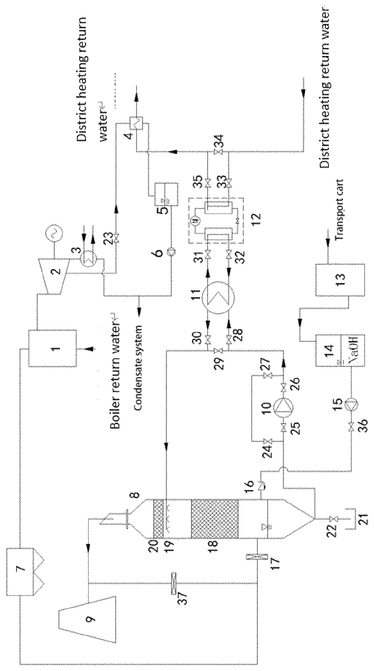
[0018]An energy-saving system using electric heat pump to recover flue gas waste heat from heat power plant for district heating is proposed. The system comprises coal-fired boilers 1, steam turbine 2, condenser 3, heat-supply network heat exchanger 4, condensate tank 5, condensate water pump 6, dust remover 7, flue gas waste heat recovery tower 8, stack 9, waste heat recovery solution pump 10, anti-corrosion and high-efficiency water-water plate heat exchanger 11, electric heat pump 12, NaOH storage tank 13, NaOH preparation device 14, NaOH solution pump 15, check valve 16, flue gas inlet valve 17, condensate pool 21, flue gas bypass valve 37, and other valves and connecting pipes.

[0019]The inner wall of the flue gas waste heat recovery tower 8 is attached with insulation material, consisting mainly of the inlet section of the flue gas, the filler l...


PUM

PropertyMeasurementUnit
Fractionaaaaaaaaaa
Fractionaaaaaaaaaa
Temperatureaaaaaaaaaa

Abstract

An energy-saving system using electric heat pump to recover flue gas waste heat for district heating uses flue gas waste heat recovery tower to absorb the sensible and latent heat in the high-temperature flue gas by direct contact heat and mass transfer. The circulating water is sprayed from the top and the flue gas flows upwards in the tower. The electric heat pump is indirectly connected with circulating water through the anti-corrosion and high-efficiency water-water plate heat exchanger. The return water of the heat-supply network enters the electric heat pump through the anti-corrosion and high-efficiency water-water plate heat exchanger and exchanges heat indirectly with the high-temperature circulating water. The electric heat pump uses the electric energy of the power plant as the driving power.

Description

BACKGROUND OF THE INVENTION[0001]The invention belongs to the technical field of flue gas purification and flue gas waste heat recovery and utilization for the coal-fired heat power plant, especially relates to a high-efficiency flue gas heat recovery system that uses electric heat pump technology to recover flue gas waste heat for district heating, and also the invention has the function of desulfurization.BRIEF DISCUSSION OF THE RELATED ART[0002]At the present stage of China's coal-fired heat power plant boiler design, exhaust temperature can reach 130° C.˜150° C., waste heat recovery potential is huge. The flue gas waste heat recovery tower with direct contact heat exchanger as the main body can deeply recover the latent heat in the flue gas by spraying cold water to the high temperature flue gas. At the same time, in the heat exchange process, the SO2 and SO3 carried by the flue gas will be dissolved in the spray circulating water, and will be treated by lye, so as to achieve th...

Claims


Application Information

Patent Timeline
IPC IPC(8): F24D10/00F24D3/18F24D19/10F28F25/02F24D12/02B01D53/50B01D53/34B01D53/78
CPCF24D10/006F24D3/18F24D19/10F28F25/02F24D12/02B01D2251/604B01D53/504B01D53/343B01D53/78B01D2251/304B01D53/502F22D11/06F23J15/02B01D2258/0283Y02E20/14Y02B30/12Y02B30/00Y02B30/17
Inventor WANG, HAICHAOWU, XIAOZHOUZHANG, RUOYUDUANMU, LINLI, XIANGLI
Owner DALIAN UNIV OF TECH
Why Eureka
Try Eureka