Furnace for endothermic process and process for operating a furnace with improved burner arrangement

a technology of endothermic process and burner arrangement, which is applied in the direction of combustion process, inorganic chemistry, lighting and heating apparatus, etc., can solve the problems of high endothermic and slow reaction, inability to meet the needs of smr reactor performance, etc., to achieve easy design, small heat, and low load

Pending Publication Date: 2022-04-14
LAIR LIQUIDE SA POUR LETUDE & LEXPLOITATION DES PROCEDES GEORGES CLAUDE
View PDF0 Cites 0 Cited by
  • Summary
  • Abstract
  • Description
  • Claims
  • Application Information

AI Technical Summary

Benefits of technology

[0036]Therefore, according to a further embodiment, the outer burners and the inner burners are configured for operating with an equal nominal firing rate. In this context, “equal nominal firing rate” means that the desired or target value for the parameter “firing rate” is equal for each burner, in particular equal for inner and outer burners. In practice, the measured firing rates may deviate from the nominal firing rates set for each of the burners of the furnace.
[0037]According to an embodiment, the inner row burners and the outer row burners are constructed identically. It is preferred to use identical burners both for outer row burners and inner row burners, for instance to ensure the same momentum flux J for the combustion products discharged from the burner nozzles. Since the number of burners of an outer burner row is reduced compared to the number of burners of an inner burner row, a smaller amount of heat will be provided to the process tube row or rows adjacent to the outer burner rows. For the case that the ratio of the number of burners of an outer burner row to the number of burners of an inner burner row is 0.5 or in a range around and comprising 0.5, for example 0.45 to 0.55, the same or at least nearly the same amount of heat will be provided to each process tube row. Since the inner and outer row burners will have the same pressure drop, the inlet manifolds for the air and the fuel streams will be easier to design. Furthermore, the inner and outer row burners will have the same response to load change with regard to air and / or fuel load, and the furnace can be run at lower loads when required. Overall, using identically constructed burners for the furnace as a whole also simplifies design of the furnace as such.
[0038]According to an embodiment, the outer burners of an outer burner row are aligned offset, at least in part, along the direction of the burner rows, to the inner burners of an inner burner row. In this connection, “aligned offset, along the direction of burner rows, to the inner burners of an inner burner row” means the following, Assumed that an imaginary line arranged perpendicular to a (parallel sided) furnace wall crosses the center of an inner row burner of an inner burner row, then the same line will not cross the center of an outer row burner of an outer burner row, because the respective outer row burner is arranged offset to the line crossing the center of the inner row burner. Outer burners of outer burner rows may be aligned offset to inner burners of inner burner rows adjacent to outer burner rows and / or further inner burners of inner burner rows non-adjacent to outer burner rows.
[0039]In a further preferred embodiment, the outer burners of an outer burner row are aligned offset, at least in part, along the direction of the burner rows, to the inner burners of an inner burner row, such that the outer burners are arranged in the middle between two inner burners of an inner burner row, preferably in the middle between two burners of an inner burner row adjacent to an outer burner row. In this connection, “in the middle” means the following. It is assumed that two imaginary lines, each line arranged perpendicular to a (parallel sided) furnace wall, respectively cross a center of two inner burners of an inner burner row. The two inner burners are arranged adjacent to each other within the inner burner row. To be arranged “in the middle” between two inner burners of an inner burner row, the outer burner is arranged such that the distance from the center of the outer burner to each one of the two lines is equal or at least essentially equal.
[0040]According to an embodiment, a distance between two inner burners of an inner burner row is IB2IB, and the distance between two outer burners of an outer burner row is OB2OB, and wherein the inner and outer burners in the rows are arranged in such a way that a ratio of IB2IB to OB2OB is 0.3 to 0.81, preferably 0.4 to 0.71 and more preferably 0.5 to 0.61. By reducing the number of burners of an outer burner row, at the same time the distances between outer burners is increased in comparison to distances between inner row burners. By reducing the number of outer burners per outer burner row and increasing the distance at the same time, heat distribution in the furnace is improved with regard to homogeneity. That is to say, a more homogenous heat profile in the furnace as a whole is accomplished.
[0041]According to an embodiment, the inner burner rows, the outer burner rows and the process tube rows are ended by vertically sided walls arranged perpendicular to the inner burner rows, the outer burner rows and the process tube rows, and wherein the inner burner rows, the outer burner rows and the process tube rows are divided into sections with the distance from an end inner burner or an end outer burner to the vertically sided wall being B2W, the distance between two adjacent inner or outer burners in the section being B2B, and half the distance in-between two sections being B2S, wherein the inner and outer burners in the rows are arranged in such a way that the ratios B2B / B2W and B2B / B2S are greater than 1.3, preferably greater than 1.6 and more preferably greater than 1.8. Such an arrangement further avoids the occurrence of the flame merging phenomenon within rows and reduces significantly the quadratic mean of the tube temperature profile, as explained in detail in European patent application EP 3 182 003 A1, which is hereby incorporated by reference as a whole.

Problems solved by technology

The reaction is highly endothermic and slow and requires additional heat input, as well as a catalyst to occur.
SMR reactor performances are usually limited by the heat transfer and not by the kinetics of the chemical reactions.
A lack of homogeneity of heat distribution in the furnace will result in some of the tubes being hotter than others, so that the performance of the furnace is limited by the temperature of the hottest tube.
Nevertheless, when this interaction between flames occurs, it is difficult to equilibrate the heat duty among the process tube rows, regardless of the level of load.
Further disadvantages are the requirement of different burner types, at least two different burners to be tested before commissioning, difficulties in pressure drop control when using different burners and difficulties in the design of the distribution system of burner streams.

Method used


Image

  • Furnace for endothermic process and process for operating a furnace with improved burner arrangement
  • Furnace for endothermic process and process for operating a furnace with improved burner arrangement
  • Furnace for endothermic process and process for operating a furnace with improved burner arrangement

Examples


Embodiment Construction

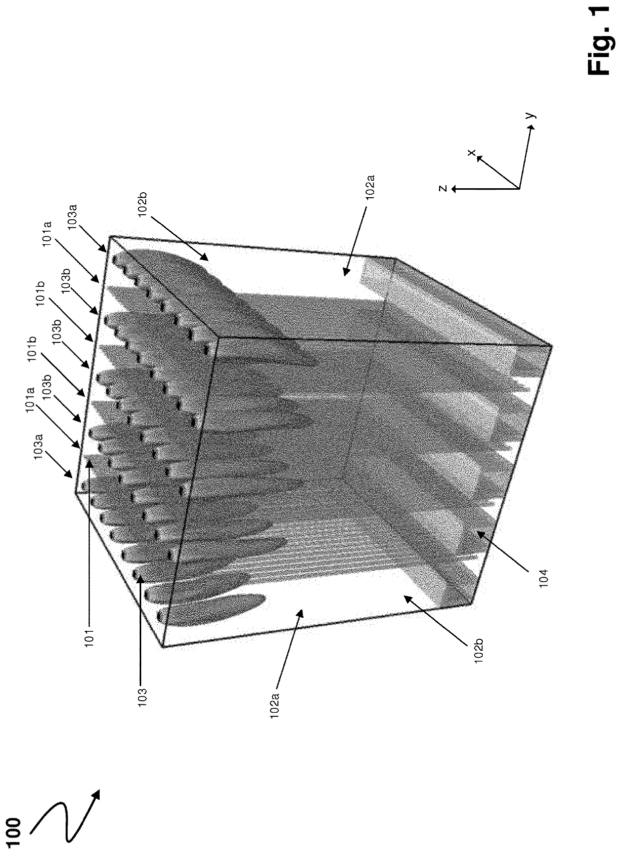
[0061]FIG. 1 shows a typical state of the art arrangement of a top-fired (down-fired) furnace 100 used to obtain a synthesis gas from a feed comprising, e.g., methane and steam. The furnace comprises facing furnace walls 102a, formed by the plane in x-z direction and facing furnace walls 102b, formed by the plane in y-z direction. All furnace walls 102a and 102b are provided with a refractory lining on their inner side.

[0062]Catalyst filled process tubes 101 are provided in four rows 101a and 101b with thirty process tubes each, each row of process tubes 101 thereby defining a process tube row. The two process tube rows 101a are arranged between and parallel to furnace walls 102a and process tube rows 101b, thereby defining outer process tube rows. The two process tube rows 101b are arranged between two process tube rows each, thereby defining inner process tube rows. Process tubes arranged adjacent to furnace walls 102b are referred to as end tubes. Each process tube row 101a, 101b...


PUM

PropertyMeasurementUnit
distanceaaaaaaaaaa
discharge velocityaaaaaaaaaa
heataaaaaaaaaa

Abstract

The invention relates to a furnace for performing an endothermic process, the furnace including a plurality of process tubes containing a catalyst for converting a gaseous feed, wherein the process tubes are arranged in rows within the furnace, each row of process tubes thereby defining a process tube row, a plurality of inner burners arranged in rows, each row of inner burners being arranged between and parallel to process tube rows, thereby defining an inner burner row, and a plurality of outer burners arranged in rows, each row of outer burners being arranged between and parallel to a process tube row and a furnace wall, thereby defining an outer burner row. A number of burners of an outer burner row is smaller than a number of burners of an inner burner row. The invention also relates to a process for operating a furnace for performing an endothermic process.

Description

CROSS REFERENCE TO RELATED APPLICATIONS[0001]This application is a 371 of PCT / EP2019 / 025367, filed Oct. 28, 2019, which claims priority to EP 18020568.4, filed Nov. 1, 2018, the entire contents of which are incorporated herein by reference.BACKGROUNDTechnical Field[0002]The invention relates to a furnace for performing an endothermic process. In particular, the present invention relates to a furnace for steam methane reforming (SMR) and other endothermic reactions like hydrocarbon feedstock cracking in externally heated reactors. The invention relates further to a process for operating a furnace for performing an endothermic process.Background Art[0003]The SMR process is mainly based on a reforming reaction of light hydrocarbon gases such as methane that yields to a mixture of hydrogen (H2) and carbon monoxide (CO) in the presence of water vapour. The reaction is highly endothermic and slow and requires additional heat input, as well as a catalyst to occur. SMR reactor performances ...

Claims


Application Information

Patent Timeline
Patent Type & Authority Applications(United States)
IPC IPC(8): F23C5/08F23C13/00C01B3/32
CPCF23C5/08F23C13/00C01B3/323C01B2203/0233C01B2203/1241C01B2203/0811F23C2900/03002C01B3/34C01B2203/0216
Inventor TADIELLO, JEAN-PHILIPPETUDORACHE, DIANA
Owner LAIR LIQUIDE SA POUR LETUDE & LEXPLOITATION DES PROCEDES GEORGES CLAUDE
Why Eureka
Try Eureka