
Alkane dehydrogenation catalyst, and hydrogen production method using same

a hydrogen production method and catalyst technology, applied in the direction of hydrocarbon preparation catalysts, physical/chemical process catalysts, bulk chemical production, etc., can solve the problems of greenhouse effect, achieve high hydrogen density, without significant energy, and produce efficiently

Pending Publication Date: 2022-08-18
OSAKA UNIV +2
View PDF0 Cites 2 Cited by
  • Summary
  • Abstract
  • Description
  • Claims
  • Application Information

AI Technical Summary

Benefits of technology

The present patent describes an alkane dehydrogenation catalyst that can extract hydrogen from an alkane without emitting CO2 and without requiring significant energy. The extracted hydrogen can be safely stored and later used as needed. The hydrogen is a renewable energy source that does not involve CO2 emission during the process from production to use. Furthermore, the hydrogen can be used as a reducing agent for nitrogen oxides to produce ammonia, a substance with high hydrogen density that liquefies under mild conditions and can be used as a fuel. Thus, the invention allows for large-scale storage and conversion of hydrogen to energy as needed.

Problems solved by technology

However, CO2 is emitted when generating electrical energy by burning fossil fuels, causing a greenhouse effect, which is problematic.

Method used


Image

  • Alkane dehydrogenation catalyst, and hydrogen production method using same
  • Alkane dehydrogenation catalyst, and hydrogen production method using same
  • Alkane dehydrogenation catalyst, and hydrogen production method using same

Examples


example 1

Production of Alkane Dehydrogenation Catalyst

Preparation of Raw Material Graphene

[0215]First, an explosive attached with an electric detonator was placed inside a pressure-resistant vessel (made of iron, volume: 15 m3) for detonation, and the vessel was sealed. As the explosive, 0.50 kg of a mixture of TNT and RDX (TNT / RDX (mass ratio)=50 / 50) was used. Next, the electric detonator was triggered, and the explosive was detonated in the vessel. Subsequently, the vessel was allowed to stand at room temperature for 24 hours, and the temperatures of the vessel and the inside of the vessel were lowered. After the cooling, a crude graphene (containing graphene and impurities generated by the detonation method described above) deposited on the inner wall of the vessel was collected.

[0216]The obtained crude graphene was washed once with water and subjected to drying under reduced pressure. Thereafter, a precipitate obtained by heating and washing with 20% hydrochloric acid and centrifuging wa...

example 2

Production of Alkane Dehydrogenation Catalyst

[0225]A catalyst (2) containing V / graphene was obtained in the same manner as in Example 1 with the exceptions that the raw material graphene used was not the graphene obtained by a detonation method but instead a multilayer epitaxial graphene synthesized by heating a SiC substrate (trade name “SiC Single Crystal wafer”, available from Nippon Steel & Sumikin Materials Co., Ltd.) at 2150° C. and that the irradiation time of argon ions was changed to 5 minutes. The amount of hydrogen contained in the catalyst (2) was 1.2×10¹⁶ atoms / cm2.

example 3

Production of Alkane Dehydrogenation Catalyst

[0226]A catalyst (3) containing VN / graphene and V / graphene was obtained using the same purified graphene as in Example 1 as the raw material graphene and in the same manner as in Example 1 with the exception that sputtering is performed by setting the position where an atomic vacancy is formed to the position of a carbon atom adjacent to a nitrogen atom in the purified graphene. The amount of hydrogen contained in the catalyst (3) was 9×10¹⁵ atoms / cm2. In addition, the nitrogen content was 4 wt. % of the total amount of the catalyst (3).


PUM

PropertyMeasurementUnit
Areaaaaaaaaaaa
Structureaaaaaaaaaa
Energyaaaaaaaaaa

Abstract

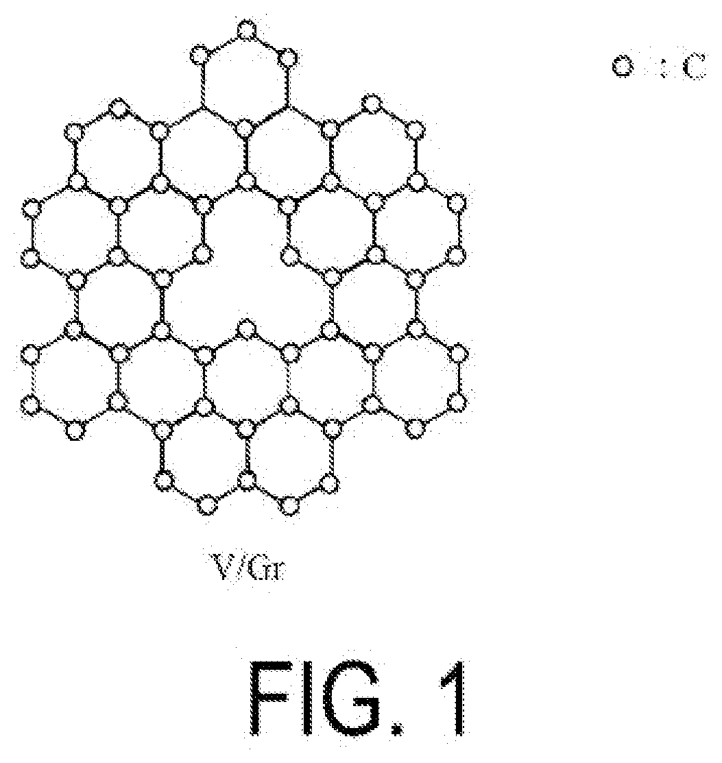
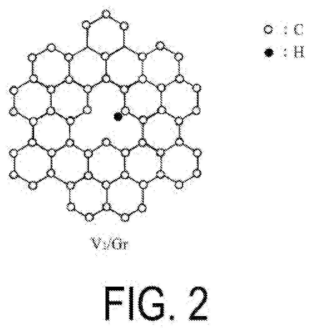
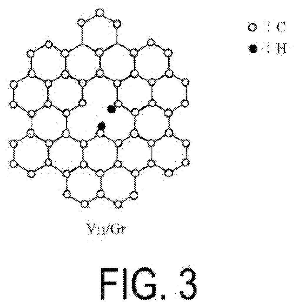
Provided are: a catalyst that is used in a reaction for producing hydrogen from an alkane without emitting CO2; a method of producing hydrogen without emitting CO2 by using the catalyst; and a method of producing ammonia using, as a reducing agent, hydrogen produced using the catalyst. The alkane dehydrogenation catalyst according to the present disclosure contains a graphene having at least one type of structure selected from an atomic vacancy structure, a singly hydrogenated vacancy structure, a doubly hydrogenated vacancy structure, a triply hydrogenated vacancy structure, and a nitrogen-substituted vacancy structure. The graphene preferably has from 2 to 200 of the structure approximately per 100 nm2 of the atomic film of the graphene. In addition, the hydrogen production method according to the present disclosure includes extracting hydrogen from an alkane by using the alkane dehydrogenation catalyst.

Description

TECHNICAL FIELD[0001]The present disclosure relates to an alkane dehydrogenation catalyst and a hydrogen production method using the catalyst. The present disclosure claims priority from the Japanese patent application No. 2019-135780, filed in Japan on Jul. 24, 2019, the contents of which are incorporated herein by reference.BACKGROUND ART[0002]Modern life has become increasingly dependent on electrical energy. However, CO2 is emitted when generating electrical energy by burning fossil fuels, causing a greenhouse effect, which is problematic.[0003]Therefore, as a renewable energy that does not emit CO2, hydrogen has been attracting attention. When combined with oxygen, hydrogen can be used to generate electricity or be burned and used as thermal energy, during which CO2 is not emitted.[0004]It is known that hydrogen, which is useful in this manner, can be produced from fossil fuels by steam reforming (Patent Document 1). It is also known that hydrogen can be produced by a carbon mo...

Claims


Application Information

Patent Timeline
IPC IPC(8): C01B3/26B01J21/18B01J37/34C01C1/02C07C5/333
CPCC01B3/26B01J21/18B01J37/341C07C2527/20C07C5/333C01B2203/068C01B2203/0277C01C1/026B01J37/08B01J37/349C01B32/184C01B32/194C07C4/10Y02P20/133Y02E60/32C07B35/04C07C2521/18B01J37/347C07C9/15C07C11/22C07C11/08B01J37/34C07B61/00Y02P20/52
Inventor KUSAKABE, KOICHITAKAI, KAZUYUKINISHIKAWA, MASAHIROLIU, MING
Owner OSAKA UNIV
Learn More