Chemically amplified positive resist composition and resist pattern forming process

a technology of amplified positive resist and composition, which is applied in the direction of photomechanical equipment, instruments, originals for photomechanical treatment, etc., can solve the problems of non-uniform distribution of pattern finish size, degradation of resolution and ler, and long time-consuming operation of successive scanning of all finely divided regions on the work surface. , to achieve the effect of reducing ler, good profile and high resolution

Pending Publication Date: 2022-09-29
SHIN ETSU CHEM IND CO LTD
View PDF0 Cites 0 Cited by
  • Summary
  • Abstract
  • Description
  • Claims
  • Application Information

AI Technical Summary

Benefits of technology

[0081]The chemically amplified positive resist composition can be processed to form a resist pattern of good profile with a high resolution and reduced LER while controlling the influence of develop loading. It is thus suited as a resist composition for forming a resist film which is sensitive to high-energy radiation such as UV, deep UV, EB, EUV, X-ray, γ-ray or synchrotron radiation and useful in the processing of semiconductor substrates and photomask blanks. The pattern forming process using the positive resist composition can form a resist pattern with a high resolution, reduced LER and controlled influence of develop loading and is thus best suited in the micropatterning technology, typically EUV or EB lithography.

Problems solved by technology

The operation of successively scanning all finely divided regions on the work surface takes a long time as compared with full wafer exposure through a photomask.
The major cause of such a change with time is diffusion of an acid generated upon exposure.
However, the base polymer having bound therein repeat units capable of generating acid upon exposure encounters a problem with respect to its solubility in organic solvent, depending on the structure and proportion of the repeat units.
However, if the diffusion of generated acid is not fully controlled, deprotection reaction can occur even in the unexposed region of the resist film, giving rise to problems like degradations of resolution and LER.
Due to the develop loading, the distribution of pattern finish size becomes non-uniform depending on the surrounding pattern feature distribution.
However, since the prior art correcting method has not fully taken into account the develop loading phenomenon for correction, the accuracy of correcting develop loading effects is not so high.
These methods are insufficient for establishing a uniform distribution of grouped and isolated features in the advanced generation of lithography.

Method used


Image

  • Chemically amplified positive resist composition and resist pattern forming process
  • Chemically amplified positive resist composition and resist pattern forming process
  • Chemically amplified positive resist composition and resist pattern forming process

Examples


synthesis example 1

[0233]Synthesis of sulfonium salt PM-1

[0234]Sodium 3,3,3-trifluoro-2-hydroxy-2-trifluoromethylpropane-1-sulfonate was synthesized according to the method of U.S. Pat. No. 8,283,104 (JP-A 2010-215608). To 132 g of an aqueous solution containing sodium 3,3,3-tifluoro-2-hydroxy-2-trifluoromethylpropane-1-sulfonate (corresponding to 0.1 mol of sodium 3,3,3-trifluoro-2-hydroxy-2-tifluoromethylpropane-1-sulfonate), 200 g of methylene chloride and 20.4 g of benzyltrimethylammonium chloride were added, followed by 30 minutes of stirring. After stirring, the aqueous solution was subjected to separatory operation, extraction and water washing. The organic layer was concentrated. Methyl isobutyl ketone was added to the concentrate, followed by concentration again. Diisopropyl ether was added to the concentrate for recrystallization. The solid precipitate was collected and dried in vacuum, yielding a benzyltrimethylammonium salt.

[0235]To the benzyltrimethylammonium salt, 15.0 g of triethylamine...

synthesis example 2-1

[0236]Synthesis of Polymer P-1

[0237]In nitrogen atmosphere, a 200-mL dropping cylinder was charged with 25.5 g of a 50.0 wt % PGMEA solution of 4-hydroxystyrene, 9.3 g of ethylcyclopentyl methacrylate, 12.7 g of 1-(1-methylcyclopentyloxy)-4-vinylbenzene, 17.5 g of PM-1, 4.1 g of dimethyl-2,2′-azobis(2-methylpropionate) (tradename V-601 by Fujifilm Wako Pure Chemical), and 24 g of γ-butyrolactone and 30 g of PGMEA as solvent to form a monomer solution.

[0238]In nitrogen atmosphere, a 300-mL flask was charged with 40 g of γ-butyrolactone and heated at 80° C. The monomer solution was added dropwise to the flask over 4 hours. After the completion of dropwise addition, the polymerization solution was continuously stirred for 18 hours while maintaining its temperature at 80° C. The polymerization solution was cooled to room temperature and added dropwise to 400 g of diisopropyl ether. The solution was statically held whereupon a solid precipitated. Diisopropyl ether was decanted off and th...

synthesis examples 2-2 to 2-58

and Comparative Synthesis Examples 1-1 to 1-2

[0239]Synthesis of Polymers P-2 to P-58 and Comparative Polymers cP-1 to cP-2

[0240]Polymers P-2 to P-58 and Comparative Polymers cP-1 to cP-2 were synthesized by the same procedure as Synthesis Example 2-1 except that the type and amount (mol %) of monomers were changed. hi Table 1, the incorporation ratio is a molar ratio.

TABLE 1IncorporationIncorporationIncorporationIncorporationIncorporationratioratioratioratioratioUnit 1(mol %)Unit 2(mol %)Unit 3(mol %)Unit 4(mol %)Unit 5(mol %)MwMw / MnP-1PM-110.0A-140.0C-125.0C-525.0——18,0001.78P-2PM-110.0A-140.0B-110.0C-120.0C-520.017,4001.79P-3PM-110.0A-140.0B-210.0C-120.0C-520.017,6001.77P-4PM-210.0A-140.0B-210.0C-120.0C-520.017,9001.78P-5PM-210.0A-140.0B-310.0C-120.0C-520.017,5001.76P-6PM-210.0A-140.0B-410.0C-120.0C-520.017,4001.78P-7PM-210.0A-140.0B-210.0C-220.0C-620.017,7001.77P-8PM-210.0A-140.0B-210.0C-320.0C-520.017,7001.75P-9PM-210.0A-140.0B-210.0C-420.0C-520.017,8001.76P-10PM-210.0A-140.0B-2...


PUM

PropertyMeasurementUnit
mol %aaaaaaaaaa
acid strength pKaaaaaaaaaaa
feature sizeaaaaaaaaaa

Abstract

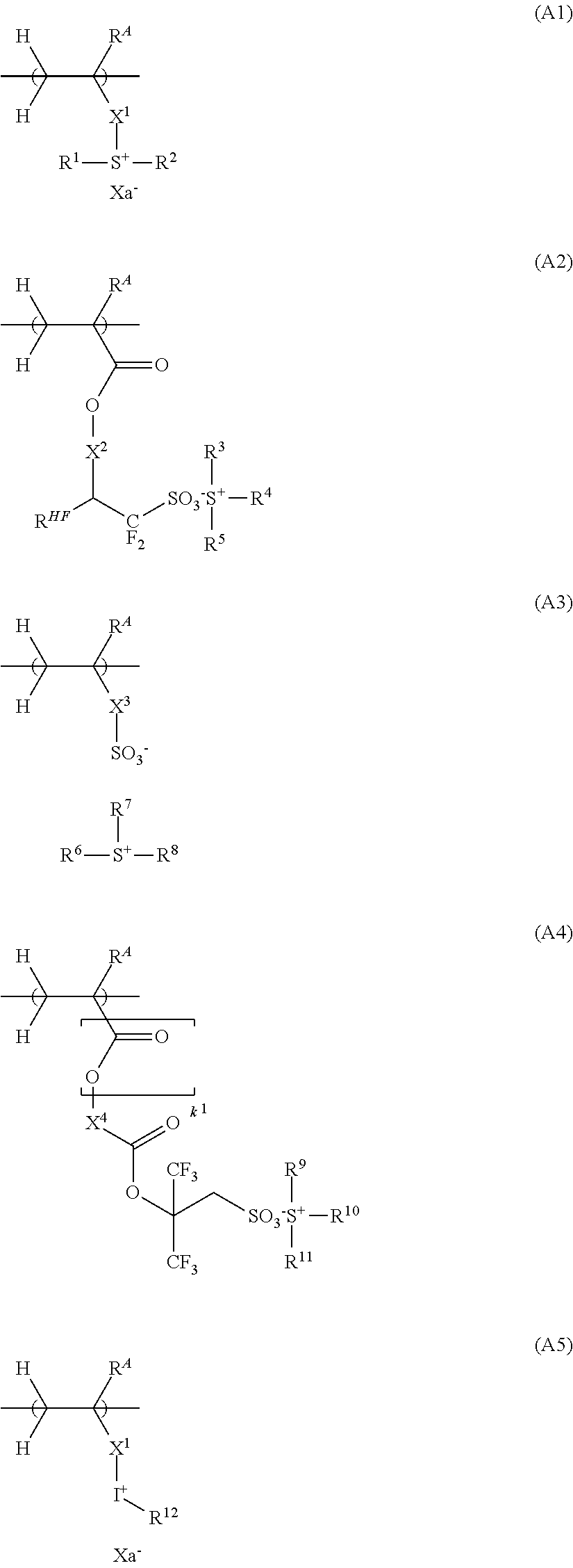
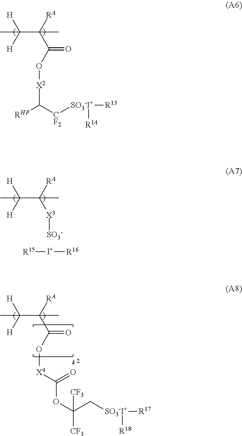
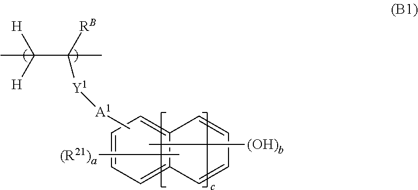
A chemically amplified positive resist composition is provided comprising a base polymer which contains a polymer comprising an acid generating unit, a phenolic hydroxy group-containing unit, a unit containing a phenolic hydroxy group protected with an acid labile group, and a unit containing a carboxy group protected with an acid labile group. A resist pattern with a high resolution, reduced LER, improved rectangularity, and minimized influence of develop loading can be formed.

Description

CROSS-REFERENCE TO RELATED APPLICATION[0001]This non-provisional application claims priority under 35 U.S.C. § 119(a) on Patent Application No. 2021-043151 filed in Japan on Mar. 17, 2021, the entire contents of which are hereby incorporated by reference.TECHNICAL FIELD[0002]This invention relates to a chemically amplified positive resist composition and a resist pattern forming process using the same.BACKGROUND ART[0003]To meet the recent demand for higher integration in integrated circuits, pattern formation to a smaller feature size is required. Acid-catalyzed chemically amplified resist compositions are most often used in forming resist patterns with a feature size of 0.2 μm or less. High-energy radiation such as UV, deep-UV, EUV or EB is used as the energy source for exposure of these resist compositions. In particular, the EB lithography, which is utilized as the ultra-fine microfabrication technique, is also indispensable in processing a photomask blank into a photomask for u...

Claims


Application Information

Patent Timeline
Patent Type & Authority Applications(United States)
IPC IPC(8): G03F7/039C08F212/14G03F1/50
CPCG03F7/0392C08F212/24G03F1/50G03F7/0395G03F7/004G03F7/0045G03F7/0046G03F7/0397C08F220/08C08F220/301C08F220/382C08F220/22C08F228/02C08F212/22G03F7/2004
Inventor MASUNAGA, KEIICHIWATANABE, SATOSHIFUNATSU, KENJIKOTAKE, MASAAKIINOUE, NAOYA
Owner SHIN ETSU CHEM IND CO LTD
Why Eureka
Try Eureka