Load demand throttle control for portable generator and other applications

a technology for portable generators and throttle control, which is applied in the direction of electric generator control, synchronous generators with multiple outputs, engine starters, etc., can solve the problems of reversing position by one or more steps, requiring a more complex and expensive microprocessor, and increasing the complexity of the system

Inactive Publication Date: 2000-01-25
PRAMAC AMERICA
View PDF60 Cites 158 Cited by
  • Summary
  • Abstract
  • Description
  • Claims
  • Application Information

AI Technical Summary

Problems solved by technology

However, use of position sensors, and associated interface circuitry increase the complexity of the system, and may require a more complex, and expensive, microprocessor.
In step motor systems, when the stepper, or coupling system is lodged against a mechanical stop, subsequent pulses cause a "bounce", resulting in a reversal of position by one or more steps.
Where a stepper motor is employed as the throttle actuator, such bumping back and forth phenomenon can cause deleterious changes in engine speed.
As previously noted, it is relatively expensive (e.g., in heat dissipation, and component power rating) to generate an analog signal that tracks the level of the relatively high voltage DC rail, directly from the DC rail itself.
Accordingly, the throttle setting is increased, causing a concomitant increase in RPM.
However, since the system is designed to provide 120 volts output during no load conditions even at idle speeds, reducing the engine speed to idle, will not itself reduce the voltage sufficiently to prevent repeated over current co

Method used


Image

  • Load demand throttle control for portable generator and other applications
  • Load demand throttle control for portable generator and other applications
  • Load demand throttle control for portable generator and other applications

Examples


Embodiment Construction

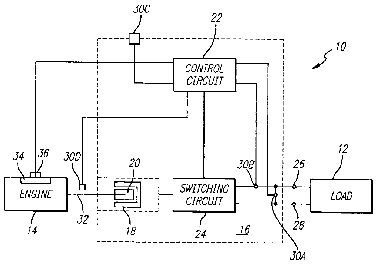
Referring now to FIG. 1, a system 10 according to various aspects of the present invention is connected to a load 12. System 10 suitably comprises an energy source 14 and a generator unit 16. Generator unit 16 suitably includes a multi-winding stator 18; a rotor 20; a control circuit 22; a switching circuit 24; output terminals 26 and 28; and at least one sensor, e.g., sensors 30A, 30B, 30C, and 30D, collectively referred to as sensors 30.

Energy source 14 may comprise any source of rotational energy, such as, for example, a conventional steam-driven turbine, a conventional diesel engine, or conventional internal combustion engine with a rotational output shaft 32 and throttle 34. Engine 14 transfers power to generator unit 16 by causing shaft 200 to rotate at a speed in accordance with the setting of throttle 34. If desired, system 10 may also include a throttle control device 36, cooperating with throttle 34. Throttle control device 36 suitably comprises an electromechanical actuat...


PUM

PropertyMeasurementUnit
Volumeaaaaaaaaaa
Timeaaaaaaaaaa
Timeaaaaaaaaaa

Abstract

The throttle of an engine in an engine driven generator system operating subject to a wide and rapidly variable load, as in supplying current to a welder, is operated such that control signals are sent to a throttle actuator for adjusting the engine throttle position in response to load changes. The throttle actuator may be a solenoid pulling against a spring in accordance with the average current through the solenoid coil. In this embodiment, the processor causes pulse width modulated signals to be applied across the solenoid coil with throttle position changes being reflected in changes to the width of the pulses, such changes in the pulse width being delayed for at least the predetermined time since the last preceding adjustment to the throttle. Alternatively, the throttle actuator may be a stepper motor which is stepped by throttle position change signals from a processor which monitors engine speed and generator load to determine whether the throttle should be adjusted and, if so, in which direction and to what extent for optimum response.

Description

The present invention relates to systems for converting mechanical to electrical energy, and, more specifically, to power conversion systems capable of accommodating a wide range of input and load conditions.In general, power conversion systems comprising a generator and an energy source, such as a motor or turbine, are well known. The generator typically comprises a rotor and stator arranged for relative rotation. Generally, the rotor is driven by the energy source, often mounted on the shaft of the motor. The rotor typically generates a magnetic field (using either permanent magnets or windings), which interacts with windings maintained on the stator. As the magnetic field intercepts the windings, an electrical current is generated. The induced current is typically applied to a bridge rectifier, sometimes regulated, and provided as an output. In some instances, the rectified signal is applied to an inverter to generate an AC output.Generators which use permanent magnets to generat...

Claims


Application Information

Patent Timeline
IPC IPC(8): H02P9/04
CPCB23K9/1062F02B75/16H02K1/278H02K1/2786H02K3/28H02K7/1815H02K11/046H02K21/48H02M7/483H02P9/04H02P9/107H02P9/14H02P9/30H02P9/48H02P25/188F02B63/04H02P2101/45F02B2063/045F02B2063/046F05C2201/021H02M7/00
Inventor ANDERSON, WILLIAM JSCOTT, HAROLD C.SUN, CHIPINGPANDYA, KANDARP I.
Owner PRAMAC AMERICA
Why Eureka
Try Eureka