Optical recording systems

a recording system and optical technology, applied in the field of optical recording systems and media, can solve the problems of increased cost and more critical tolerances, adverse effects on reading and writing operations, and expensive optical storage systems 30, and achieve the effects of enhancing the signal-to-noise, or contrast, of written optical artifacts, and reducing the cost and critical tolerances

Inactive Publication Date: 2000-07-25
SENSHIN CAPITAL +1
View PDF8 Cites 72 Cited by
  • Summary
  • Abstract
  • Description
  • Claims
  • Application Information

AI Technical Summary

Benefits of technology

Also of importance to optical storage density is the contribution of the exponential vertical decay of the near-field. This exponential decay makes the contrast of the written optical artifacts extremely high, as the signal changes from total reflection of the illumination to almost total transmission with, in the case of actual optical artifacts, a depth change of only 0.2 microns. In the case of the phase change material, the contrast is also increased. The near-field illumination reduces surface or F

Problems solved by technology

However, this approach results in an increase in cost and more critical tolerances resulting from a shallower depth of field.
Most problematic is that the operations of reading and writing are adversely affected by the presence of contamination on medium surface because the flying height of aplanatic sphere 31 is made to exceed the sensible extent of ev

Method used


Image

  • Optical recording systems
  • Optical recording systems
  • Optical recording systems

Examples


first embodiment

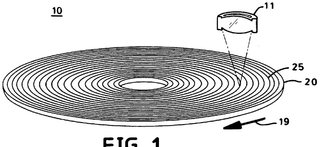
In a first embodiment, as best seen in FIGS. 21 and 22, data is written to or read from a storage medium 140 comprising an optical layer 153 integral with an active layer 143 preferably disposed upon a substrate 141. In the configuration shown, storage medium 140 is disc-shaped, and optical layer 153 comprises a plurality of concentric or spiral lenticular lenses (see for example, FIG. 23) wherein storage medium 140 is rotated for the reading and writing of data. In an alternative embodiment (see FIG. 24), storage medium 140 may be rectangular in shape with data retrieval and storage accomplished by means of rotation or rectilinear motion, for example. Alternatively, storage medium 140 can be stationary with data retrieval accomplished by means of a whole-field imaging detector array. Storage medium 140 may be disposed within an optional protective housing 105, as shown. Housing 105, which serves to minimize the possible contamination of active layer 143, comprises an optically-tran...

second embodiment

In a second embodiment, as best seen in FIGS. 26 and 27, data is written to or read from a storage medium 160 comprising a housing 171, an optical-layer window 173, and an active layer 163 preferably disposed upon a substrate 161. As best seen in FIG. 28A, a data bit is represented by the presence or absence of one or more optical artifacts 167 detected within a data surface 165. Active layer 163 and substrate 161 are disposed within housing 171. Optical-layer window 173 comprises a distributed structure of micro-optical elements 175, such as an array of lenticular lenses (as shown) or alternatively, an array of micro-lenses. During the process of detecting or producing optical artifacts 167, active layer 163 is translated relative to objective lens 111, as indicated by arrow 19, and data is written to or read from active layer 163 through optical-layer window 173.

During the read / write processes, reflection surface 177 of optical-layer window 173 is retained at a substantially fixed...


PUM


Abstract

An optical storage system suitable for optical storage and retrieval of information using a storage medium comprising a substrate, an active layer for retention of the data, and an overlying optical layer, or layers for double-sided. The optical layer serves to produce an evanescent field in or adjacent to the active layer in response to an incident beam of radiation. The evanescent field is frustrated or attenuated by the data in the active layer and produces a signal.

Description

1. Field of the InventionThis invention in general relates to the field of optical recording systems and media and, in particular, to an optical storage system using media comprising integral near-field optics by which means a greater resolution and storage density is attained in the processes of writing to and reading from a recording layer.2. Description of the Prior ArtIn near-field optical applications, splitting off the total internal reflection (TIR) surface from the aplanatic immersion lens in an imaging objective and integrating it with the object to be viewed is taught in Guerra, Applied Optics 1990 and SPIE 1988, and in a flexible form (transducer) in Guerra, J. M., Flexible Transducers for Photon Tunneling Microscopes and Methods for Making and Using Same, U.S. Pat. No. 5,349,443, Sep. 20, 1994 assigned to Polaroid Corp., Guerra, J. M., Stereoscopic Photon Tunneling Microscope, U.S. Pat. No. 5,442,443, Aug. 15, 1995 assigned to Polaroid Corp, and Guerra, J. M., Method for...

Claims


Application Information

Patent Timeline
IPC IPC(8): G11B23/03G11B7/12G11B7/004G11B7/00G11B7/125G11B7/24G11B7/135G11B7/0065G11B11/00G11B11/105G11B7/26G11B7/14
CPCB82Y10/00G11B7/004G11B7/12G11B7/1353G11B7/1365G11B7/1372G11B7/1381G11B7/1387G11B7/24G11B23/0316G11B7/0065G11B7/14G11B7/26G11B11/10532G11B11/1055G11B11/10584G11B2007/0013Y10S977/773Y10S977/834Y10S977/712Y10S977/943G11B7/24065G11B11/105
Inventor GUERRA, JOHN M.
Owner SENSHIN CAPITAL
Why Eureka
Try Eureka