Etching process

a technology of etching process and etching electrode, which is applied in the field of etching process, can solve the problems of affecting the accuracy of pattern formation

Inactive Publication Date: 2000-12-19
CANON KK
View PDF10 Cites 12 Cited by
  • Summary
  • Abstract
  • Description
  • Claims
  • Application Information

AI Technical Summary

Problems solved by technology

Further, if the Cu layer 22 is etched excessively, the resultant metal electrodes are liable to lose their function as (auxiliary) electrodes for the liquid crystal panel in some cases.
However, such an etchant is liable to dissolve the Cu layer, thus causing a partial peeling of an etching (resist) mask covering the Cu layer thereby to hinder accurate pattern formation.
In the case of the etchant described in JP-A 8-311663, the etching temperature of the etchant is increased due to inclusion of peroxide, thus resulting in a difficulty of temperature control.
Accordingly, it becomes difficult to control the above-mentioned temperature-dependent etching rate, thus failing to make etching qualities constant in a mass-production process.
The addition of (fresh) peroxide, however, changes the composition or concentration of the etchant, thus leading to a change in etching rate.
As a result, etching qualities in a mass-production process are liable to be rendered nonuniform.
The metal electrode made of Cu, however, has a poor adhesiveness to the glass substrate and is readily oxidized as described above.
This is because a layer of Ni is preferred for the purposes of improvement in adhesiveness and prevention of oxidation but is accompanied with the following problem.
However, the thinner Ni target is required to be frequently replaced in the case of mass production, thus lowering production efficiency.
In the case of a multi-layer metal structure including an adhesive layer and/or anti-oxidant layer comprising Mo, however, etching of such Mo-containing l...

Method used


Image

  • Etching process
  • Etching process
  • Etching process

Examples


first embodiment

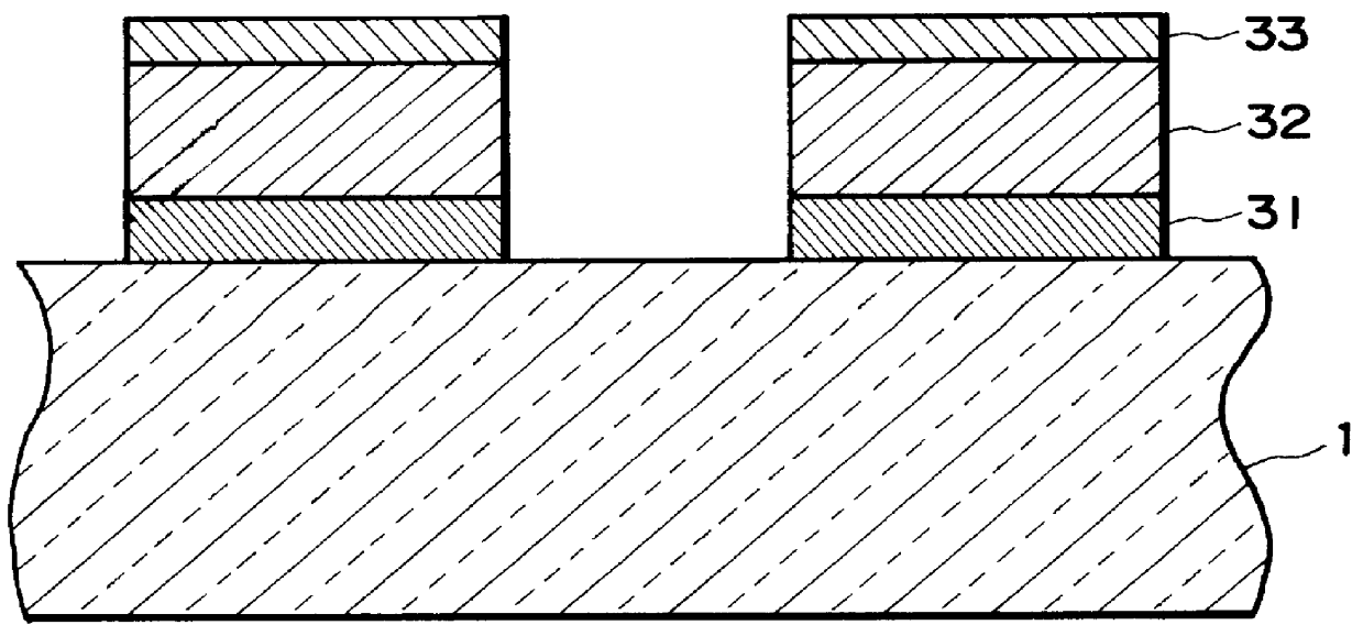
According to this example, it was possible to achieve effects similar to those described in Specifically, although the etching time was fluctuated within .+-.2 sec and the etching temperature was fluctuated between 20.degree. C. and 30.degree. C., no burr portions occurred due to a uniformity of etching rates between the first to third (Ni / Cu / Ni) layers 31, 32 and 33.

example 2

A multi-layer metal structure including a 400 .ANG.-thick first layer 31 of Ni-Mo alloy (Mo=10 at %), a 10.sup.4 .ANG.-thick second layer 32 of Cu, and a 400 .ANG.-thick third layer 33 of Ni-Mo alloy (Mo=10 at %) was formed on a glass substrate 1 by a magnetron sputtering process in the same manner and conditions as in Example 1 except that the film-forming times of the first layer 31 (60 sec) and the third layer 33 (120 sec) were changed to 70 sec.

THe thus formed multi-layer metal structure was etched in the same manner as in Example 1 except that the etchant was changed to an etchant and the spin etching was changed to line etching described below, respectively.

The etchant used in this example was prepared by diluting with pure water a ferric chloride aqueous solution (42.degree. Be') at a dilution ratio (aqueous solution:water=1:24 by volume) and by adding 1,2,3-benzotriazole in the diluted aqueous solution at a concentration of 1 g / l, followed by sufficient dissolution thereof...

example 3

A multi-layer metal structure including first to third layers 31, 32 and 33 was formed on a glass substrate 1 in the same manner as in Example 2.

The thus formed multi-layer metal structure was etched in the same manner as in Example 2 except for using an etchant prepared in the following manner.

The etchant was prepared by diluting with pure water a mixture solution of a hydrochloric acid solution of ferrous chloride (30 w / w %) and a ferric chloride aqueous solution (42.degree. Be') (1:1 by volume) at a dilution ratio (mixture:water=1:24 by volume) and by adding thiocyanuric acid (1,3,5s-triazine-2,4,6-trithiol) in the diluted mixture solution at a concentration of 1 g / l, followed by sufficient dissolution with ultrasonic wave.

According to this example, similar effects as in Example 1 were achieved.


PUM

PropertyMeasurementUnit
Volumeaaaaaaaaaa
Volumeaaaaaaaaaa
Volumeaaaaaaaaaa

Abstract

An etching process includes the steps of: preparing an etchant containing ferric chloride and an anticorrosive agent for Cu, and etching with said etchant a multi-layer metal structure including a Cu layer and an Ni layer. The etchant may preferably further contain ferrous chloride. The etching process is effective in making etching rates of the respective substantially equal, thus suppressing occurrence of burr portions of the Ni layers.

Description

FIELD OF THE INVENTION AND RELATED ARTThe present invention relates to an etching process for etching a multi-layer metal structure comprising at least a layer of copper (Cu).There have been proposed various etching processes for etching a multi-layer metal structure including, e.g., a layer of Cu or Cu alloy and a layer of nickel (Ni) or Ni alloy.Such a multi-layer metal structure including a Cu layer and an Ni layer may generally be used as a metal electrode for use in a liquid crystal panel. Specifically, the liquid crystal panel includes a pair of glass substrates for sandwiching a liquid crystal therebetween and a plurality of metal electrodes formed on the surface of the glass substrate(s). Each of the metal electrodes may be formed in a plurality of layers including a Cu layer and an Ni layer.The Cu layer constituting the metal electrodes is effective in increasing a liquid crystal drive speed due to a small electrical resistance of Cu, thus allowing a large picture area and ...

Claims


Application Information

Patent Timeline
IPC IPC(8): C23F1/18C23F1/28C23F1/10G02F1/13G02F1/1343H05K3/06
CPCC23F1/18C23F1/28H05K3/067G02F1/13439H05K2201/0338
Inventor ISHIKURA, JUNRIYOSHIKAWA, TOSHIAKI
Owner CANON KK
Why Eureka
Try Eureka