Pressure vessel and process for producing the same

Inactive Publication Date: 2001-02-20
TORAY IND INC
View PDF17 Cites 98 Cited by
  • Summary
  • Abstract
  • Description
  • Claims
  • Application Information

AI Technical Summary

Benefits of technology

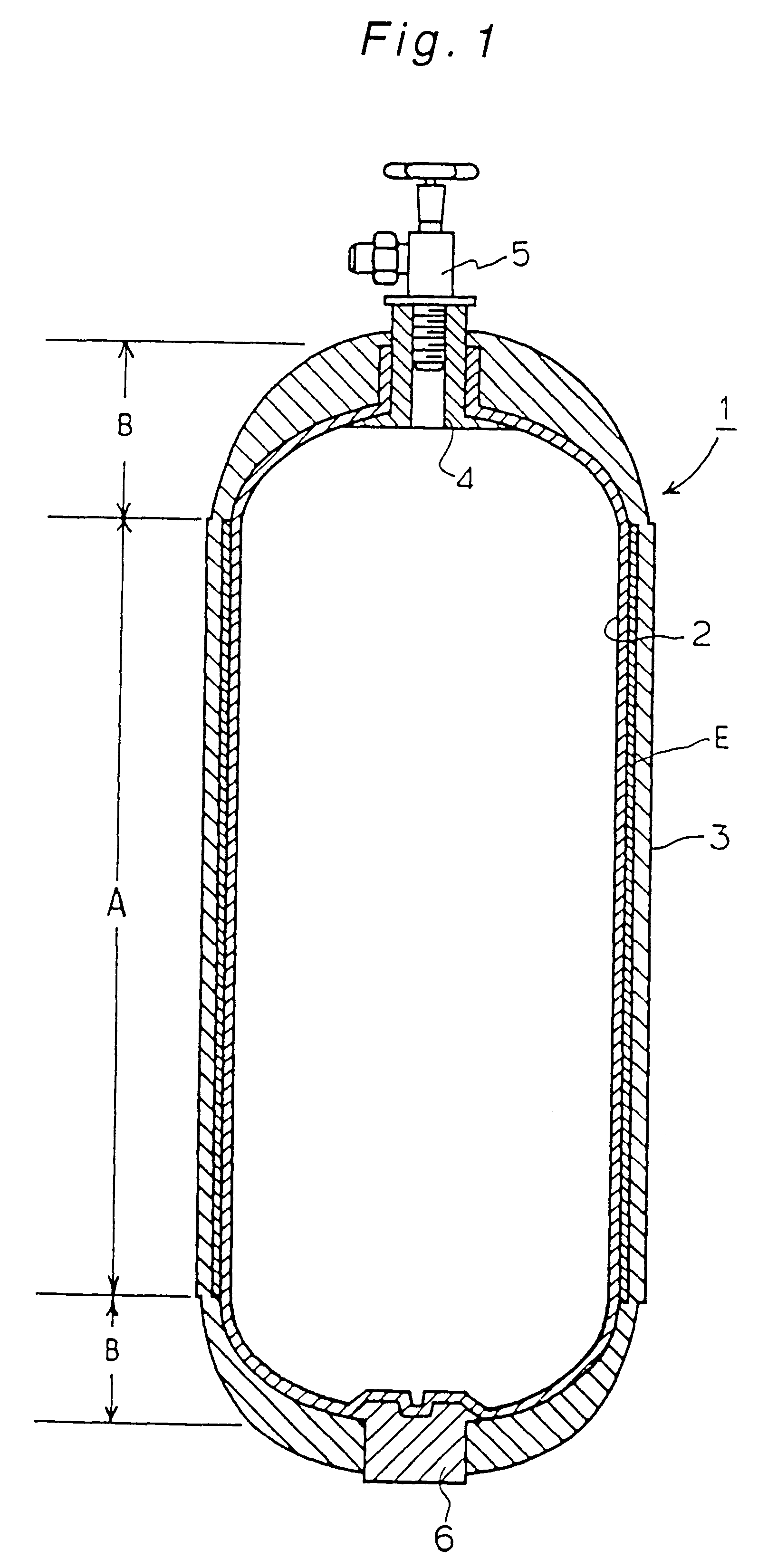
Also in this configuration, since the flange portion 95c of the cylindrical member 95 is fixed and supported by the outer shell 95, most of an external load acting on the boss 4 is directly received by the cylindrical member 95, and the falling-off of the boss 4 is reliably prevented. Furthermore, to enhance the coupling strength between the inner shell and the cylindrical member, for further increasing the fixing strength of cylindrical member, an adhesive can be applied between the cylindrical member and the circumferential surface of the boss of the inner shell, and between the seal ring and the faces to receive the seal ring pressed, for enhancing the coupling strength. The adhesive can be selected from those previously listed.
On the other hand, if the pressure vessel of the present invention has a configuration such that the boss for nozzle installation is pro

Problems solved by technology

The conventional pressure vessels for motor vehicles are made of a metal such as steel or aluminum alloy, but a pressure vessel made of a metal is heavy and shortens the drivable distance of the motor vehicle per unit weight of the fuel supplied to the motor vehicle.
This also increases the total weight of the motor vehicle, to further shorten the drivable distance of the motor vehicle.
However, on the other hand, since an FRP is fragile as compared with a metal, an impact due to a collision or any other cause can cause the pressure vessel to be burst instantaneously, to injure human bodies by its broken pieces or to cause an explosive fire due to leak of natural gas.
Furthermore, if the pr

Method used


Image

  • Pressure vessel and process for producing the same
  • Pressure vessel and process for producing the same
  • Pressure vessel and process for producing the same

Examples


Example

Example 1

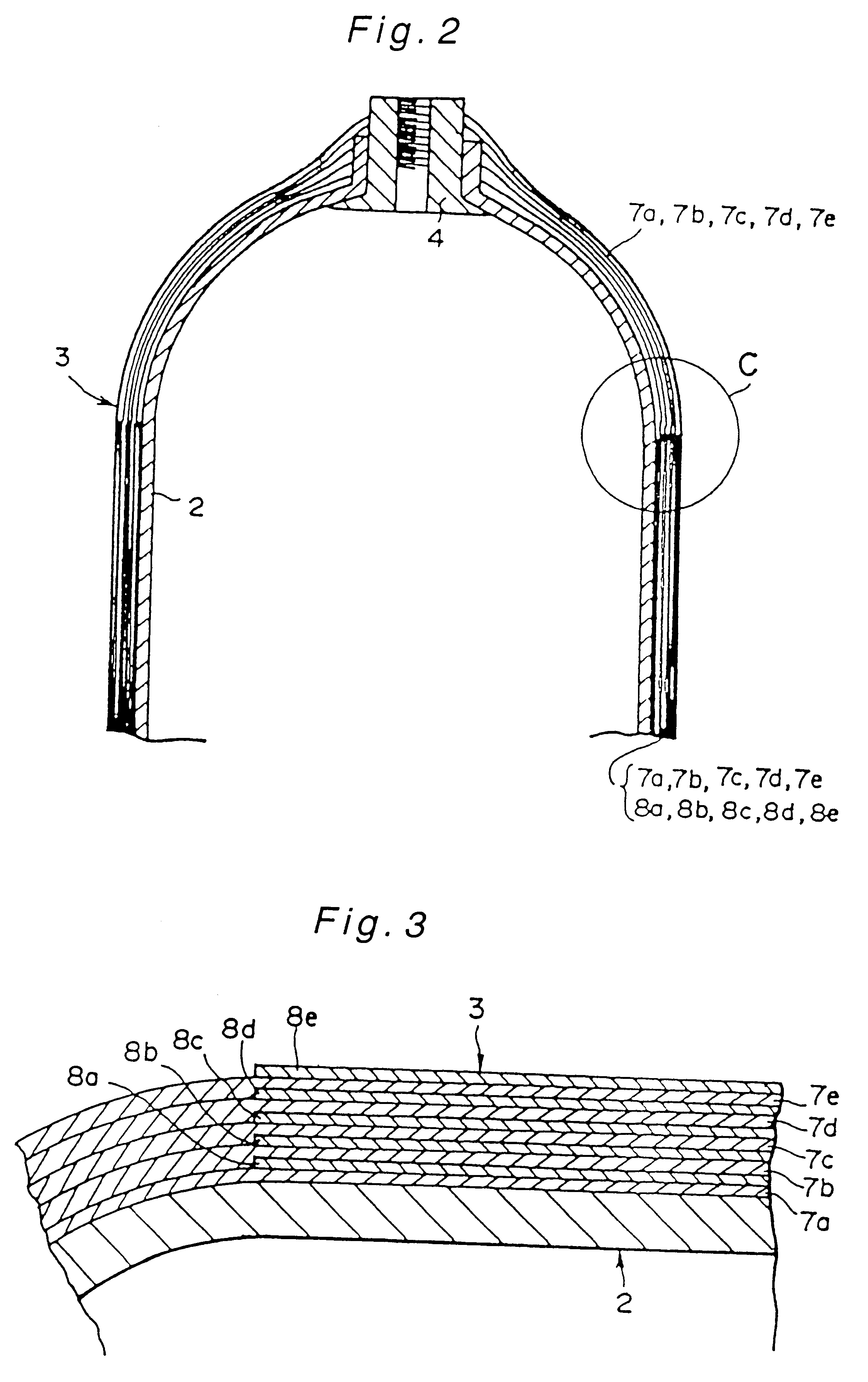
A blow-molded inner shell (200 mm in outer diameter, 1,000 mm in the overall length excluding the nozzle installation portion, and 2 mm in wall thickness) made of high density polyethylene resin was used as a mandrel, to form an outer shell on an inner shell by a filament winding method. For the filament winding, a carbon fiber yarn (12,000 filaments of 7 .mu.m in single fiber diameter, 4.6 GPa in tensile strength, and 2.2% in tensile breaking strain) impregnated with an epoxy resin (4% in tensile breaking strain) was wound to form a .+-.3.degree. layer, 88.degree. layer, and .+-.45.degree. layer (the angles are with reference to the axial direction of the pressure vessel) in this order, with the volume ratio of the carbon fiber yam in the .+-.3.degree. layer: that in the 88.degree. layer: that in the .+-.45.degree. layer kept at 1:2:2, and the inner shell with the carbon fiber yarn wound around it was heated at 130.degree. C. in an oven for 6 hours, to form the main body o...

Example

Comparative Example 1

A main body was obtained as described in Example 1, except that the carbon fiber yarn used had 12,000 filaments of 7 .mu.m in single fiber diameter, a tensile strength of 3.0 GPa and a tensile breaking strain of 1.3%. The outer shell was 51 GPa in tensile modulus and 1.2% in tensile breaking strain.

The main body was tested as described in Example 1, and the damaged area was 7.2 cm.sup.2, and the ratio of pressures withstood before and after the impact test was 0.55.

Example

Comparative Example 2

A main body of a pressure vessel was formed as described in Example 1, except that the carbon fiber yarn used had 12,000 filaments of 7 .mu.m in single fiber diameter, a tensile strength 2.4 GPa, and tensile breaking strain of 1.6%, that an E glass fiber yarn of 9 .mu.m in single fiber diameter, 3.5 GPa in tensile strength, and 4.8% in tensile breaking strain was used, and that .+-.3.degree. layer of the carbon fiber yarn, an 88.degree. layer of mixed carbon fiber yarn and E glass fiber yarn, and a .+-.45.degree. layer of the carbon fiber yarn (the angles are with reference to the axial direction of the pressure vessel) were formed in this order, with the volume ratio of the fiber in the .+-.3.degree. layer: that in the 88.degree. layer: that in the .+-.45.degree. layer maintained at carbon fiber yarn: {carbon fiber yarn: E glass fiber yam}: carbon fiber yarn=1:{1:1}:2. The outer shell thus obtained was measured according to the NOL ring testing method, and foun...


PUM

PropertyMeasurementUnit
Fractionaaaaaaaaaa
Fractionaaaaaaaaaa
Fractionaaaaaaaaaa

Abstract

The pressure vessel of the present invention comprises an inner shell capable of serving as a gas barrier and a pressure resistant outer shell provided to cover the inner shell, said outer shell being made of an FRP comprising reinforcing fibers and a resin and is 35 GPa or more in tensile modulus and 1.5% or more in tensile breaking strain. The present invention can provide a pressure vessel not only light in weight, but also excellent in retaining its internal pressure against repetitive impacts and also excellent in reliability. The process for producing a pressure vessel of the present invention comprises the step of forming a pressure resistant outer shell made of an FRP comprising reinforcing fibers and a resin and is 35 GPa or more in tensile modulus and 1.5% or more in tensile breaking strain, around an inner shell capable of serving as a gas barrier, by a filament winding method or a tape winding method. The present invention can produce a pressure vessel excellent in retaining its internal pressure, excellent in reliability, and light in weight at a low cost.

Description

The present invention relates to a pressure vessel used for various applications, especially pressure vessels suitable for installation in motor vehicles, etc.In recent years, motor vehicles using natural gas as a fuel have attracted attention as low-pollution vehicles. Such a motor vehicle is mounted with a pressure vessel generally called a CNG tank (compressed natural gas tank).The conventional pressure vessels for motor vehicles are made of a metal such as steel or aluminum alloy, but a pressure vessel made of a metal is heavy and shortens the drivable distance of the motor vehicle per unit weight of the fuel supplied to the motor vehicle. In addition, since the calorific value of natural gas per unit weight is only about one half that of gasoline, the quantity of natural gas which must be stored in a motor vehicle must be about double as compared with gasoline, if the drivable distance without additional fuel supply is to be kept as long as that for gasoline. This also increase...

Claims


Application Information

Patent Timeline
IPC IPC(8): B29C53/80B29C53/00B29C70/00B29C70/86F17C1/00F17C1/16B32B1/08F17C1/06
CPCB29C53/8016B29C70/382B29C70/86F17C1/06F17C1/16B29C53/602B29K2707/04B29K2709/08B29L2031/7156F17C2201/0109F17C2201/056F17C2203/012F17C2203/0604F17C2203/0621F17C2203/0624F17C2203/0636F17C2203/066F17C2203/0665F17C2203/067F17C2203/0673F17C2205/0305F17C2205/0329F17C2205/0394F17C2209/2118F17C2209/2127F17C2209/2154F17C2209/227F17C2209/232F17C2221/011F17C2221/014F17C2221/033F17C2223/0123F17C2223/036F17C2260/011F17C2260/012F17C2260/042F17C2270/0168B29C70/16B29D22/00
Inventor IIDA, YASUSHIKITANO, AKIHIKOYAMAGIWA, MASAYOSHIKOBAYASHI, MASANOBUNOGUCHI, KENICHI
Owner TORAY IND INC
Why Eureka
Try Eureka