

Method for separating biological substances by using photoresist
a biological substance and photoresist technology, applied in the field of biological substance separation by using photoresist, can solve the problems of difficult to completely burn away portions other than the target cell or tissue using a laser, requires a highly-skilled and experienced technician, and cannot be collected only without contamination. , to achieve the effect of preventing unsatisfactory effects
- Summary
- Abstract
- Description
- Claims
- Application Information
AI Technical Summary
Benefits of technology
Problems solved by technology
Method used
Image


Examples
second example
Separation Method Using Amphoteric Photoresist
The method of a second example is schematically shown in FIGS. 4(a) to 4(f).
(2-1) Fix Cells Using Photoresist
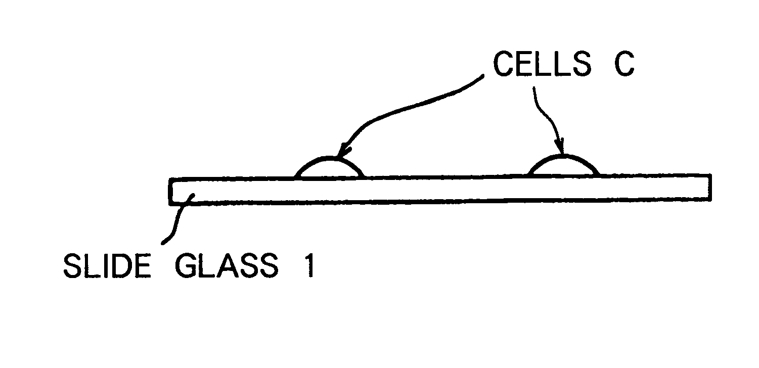
In the same manner as per 1-1 of the first example, cells C were prepared by cultivation in a single layer on a slide glass 1 as shown in FIG. 4(a). It should be noted that the photoresist SPR6112 used in the first example also serves as an amphoteric photoresist.
After 300.mu. 1 of photoresist 2 (SPR6112 produced by Shipley Co.) was added onto the slide glass 1, the slide glass 1 was heated for several minutes at 95.degree. C. to solidify the photoresist 2 as shown in FIG. 4(b). The layer of the solidified photoresist 2 was approximately 7 .mu.m thick. It was confirmed that the cells C can be stored in this condition for a month or more.
(2-2) Collection of Target Cell
The obtained sample was transferred to under a fluorescence microscope (Axioplan model produced by Carl Zweiss), the cells were observed using differential interferen...
third example
Separation Method Using Negative Photoresist
A method of a third example is schematically shown in FIGS. 5(a) to 5(e).
(3-1) Collection of Target Cell
In the same manner as per 1-1 of the first example, cells C were prepared by cultivation in a single layer on a slide glass 1 as shown in FIG. 5(a).
300 .mu.l of photoresist 2 (Model OMR85 produced by Tokyo Ohka Kogyo Co., Ltd.) was added onto the slide glass 1, and the photoresist 2 was solidified in the same manner as per 1-1 of the first example.
The cells covered with the photoresist was transferred to under a fluorescence microscope (Axioplan model produced by Carl Zweiss), the cells were observed using differential interference techniques, and a target cell was determined.
Next, the area of the photoresist other than the portion thereof that includes the target cell was irradiated for about 10 seconds with 440 nm wavelength light L using a high pressure mercury lamp as shown in FIG. 5(c).
As shown in FIG. 5(d), 10 .mu.l of xylene (solu...
fourth example
Separation Method Using Positive Photoresist (2)--Considerations With Respect to Suspended Cells
NIH / 3T3 cells derived from mouse were cultivated in a DMEM (10% addition fetal bovine serum) culture medium in a culture Petri dish at 37.degree. C. and in a 5% CO.sub.2 atmosphere. Next, the cells were subjected to trypsinization to prepare suspended cells. The cells were washed two times in PBS. Then, a cell suspension was prepared by adjusting the cell count to 5.times.10.sup.5 cells / ml. Next, 10 .mu.l of the cell suspension was added to 90 .mu.l of positive photoresist liquid (SPR6112 produced by Shipley Co.) and mixed by lightly pipetting the two liquids. Afterward, the mixture was added to a slide glass and the mixture was spread by tilting the slide glass. The photoresist was formed into a layer by heating for 30 minutes at 45.degree. C. In the same manner as in the first example, the obtained sample was irradiated under a fluorescence microscope with 440 nm light for 50 cells as t...
PUM
| Property | Measurement | Unit |
|---|---|---|
| temperature | aaaaa | aaaaa |
| temperature | aaaaa | aaaaa |
| temperature | aaaaa | aaaaa |
Abstract
Description
Claims
Application Information