Artificial dielectric device for heating gases with electromagnetic energy

a dielectric device and electromagnetic energy technology, applied in the direction of electric/magnetic/electromagnetic heating, energy-based chemical/physical/physical-chemical processes, separation processes, etc., can solve the problems of limited above-effects and the inability of the susceptor's structure to allow the applied energy to penetrate into the entire volume, etc., to achieve faster heating rate, reduce the time to, and improve the effect of heat dissipation

Inactive Publication Date: 2001-08-07
DALTON ROBERT C
View PDF32 Cites 21 Cited by
  • Summary
  • Abstract
  • Description
  • Claims
  • Application Information

AI Technical Summary

Benefits of technology

Example Three: If a combination of treatment methods is needed as the best method for either chemical reaction or destruction of pollutants, then adsorption, transmission, reflection and scattering of electromagnetic energy or energies by the susceptor may be required. Absorption of the applied electromagnetic energy in the susceptor could either produce heat, produce fluorescent radiation emissions, thermoluminescent radiation emissions or assist in producing fluorescent radiation. For example, an applied ultraviolet (UV) energy source can be used to produce phosphorescent radiation in a susceptor or at a field concentrator for interaction between the phosphorescent radiation and the gaseous / particulate species to drive the reaction. The applied UV energy can also interact with the gaseous / particulate species. Such a material for the susceptor or field concentrator could be a phosphorescent material. The depth of penetration of susceptor must allow for applied UV energy to penetrate the susceptor for volumetric interaction a) with the susceptor to produce fluorescent radiation and / or b) direct interaction between the applied UV energy and gaseous / particulate species. Consequently, if UV and microwave energies are applied to the same susceptor other interactions may occur between the applied energies, material of construction of the susceptor, field concentrators and the gaseous species (or particulate). The UV energy which is applied to the cavity can interact as previously mentioned, however the microwave energy may a) produce thermoluminescence in the phosphoresent materials b) produce heat in the susceptor by the applied microwave energy may enhance the phosphoresent radiation produce primarily by the applied UV energy. Of other consequence, if the applied energy to the same susceptor is only microwave energy then other interactions may occur. The microwave energy may either a) be completely absorbed for thermal treatment of the gases, b) be partially absorbed and interact with the gaseous species for interaction, c) be used to heat the susceptor and produce thermophosphorescence of UV radiation which interacts with the gaseous species or d) a combination of the mentioned interactions in a, b, and c.
The thermal conductivity of the unit susceptor can be controlled for heat transfer. The thermal conductivity can be controlled by either a) porosity of the material of the unit susceptor, b) the composite structure of the unit susceptor, c) high thermally conductive materials such as from high purtiy nitrides, aluminides, suicides, borides and carbides d) highly thermally conductive coatings can be used as coating on porous unit susceptors to increase the thermal conductivity at the surface or e) grading the pore structure by flame polishing the outer surface of the susceptor.

Problems solved by technology

However, these above effects are limited and influenced by the size, shape, conductivity and volume fraction of the material embedded in a materials of low dielectric loss, low dielectric constant of the material as well as the wavelength of the incident radiation.
If so, the susceptor's structure will not allow for the applied energy to penetrate into the entire volume of SiC granules.

Method used


Image

  • Artificial dielectric device for heating gases with electromagnetic energy
  • Artificial dielectric device for heating gases with electromagnetic energy
  • Artificial dielectric device for heating gases with electromagnetic energy

Examples


Embodiment Construction

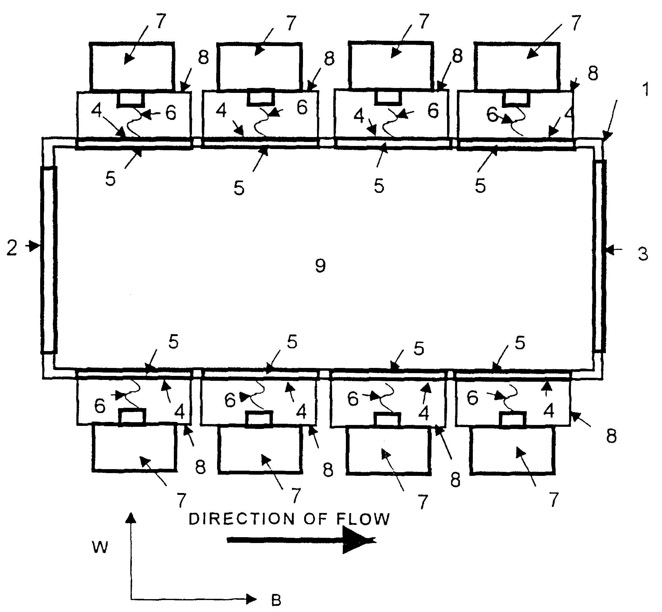
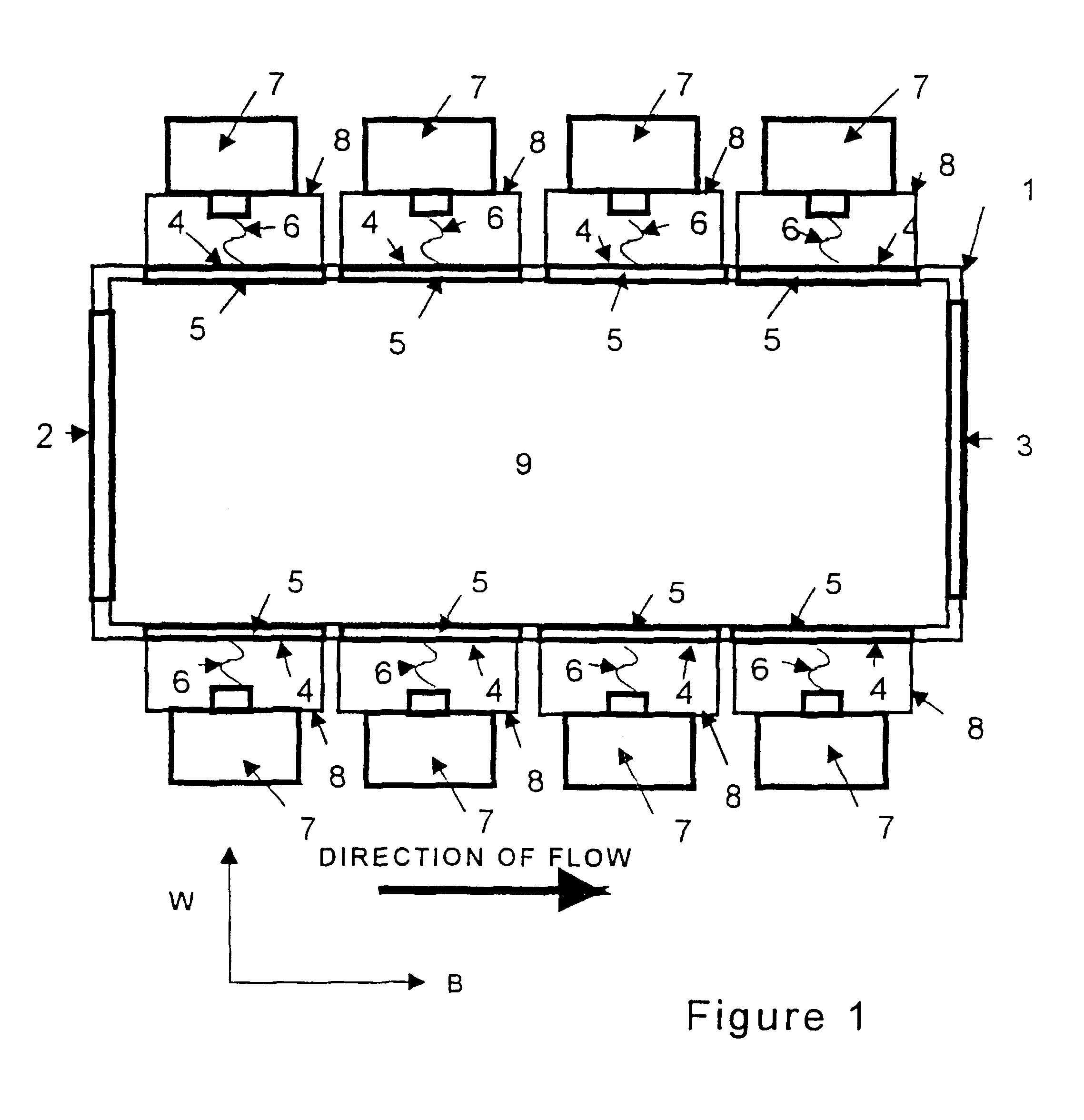
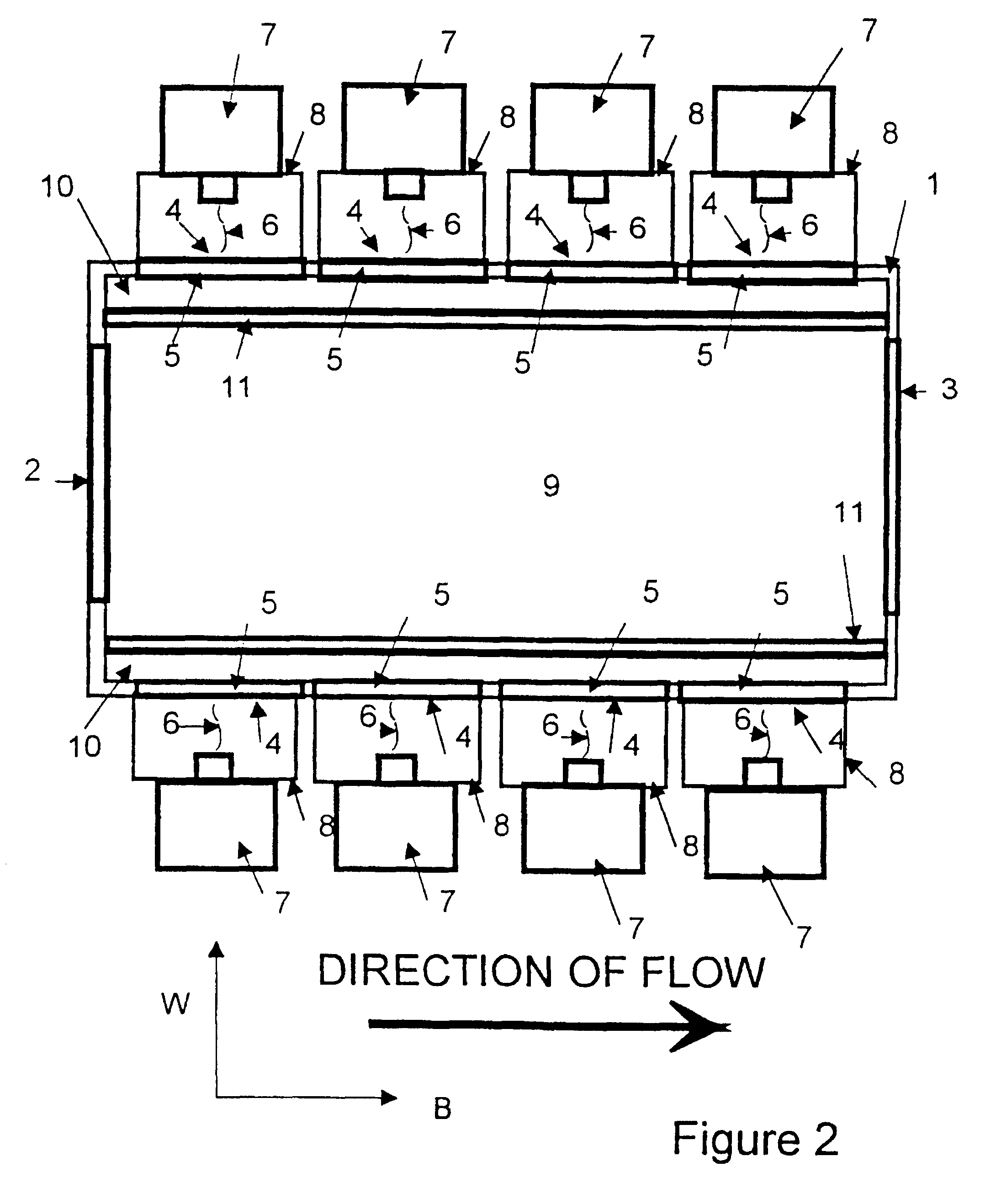
This invention is a device which uses a gas-permeable structure for a susceptor of electromagnetic energy to react gases for desired products or to treat pollutants for producing clean air which can be discharge into the environment in accordance with the law of the land. The device has a specific cavity geometry, location where the of the applied energy from a source enters the cavity, a susceptor that is designed by the depth of penetration of the susceptor, and a means to scale-up the device for larger flow rates of an air stream without changing the susceptor's interaction with the applied energy or depth of penetration of the susceptor because the device is designed to increase the size of the device by a near linear scale from the location of the where the applied electromagnetic energy enters the cavity and the cavity's geometry.

Another aspect of this invention is a heat transfer process that increases the efficiency of the device.

Another aspect of this invention is a gas-per...


PUM

PropertyMeasurementUnit
thicknessaaaaaaaaaa
thicknessaaaaaaaaaa
diameteraaaaaaaaaa

Abstract

A device for thermal treatment of gases and pollutants employs alternate cavity (1) and susceptor (9) geometries for providing more homogeneous interactions of applied electromagnetic energy (6) in the volume of the susceptor (9) regardless of the flow rate and diameter of the exhaust duct (3) width. The heat transfer methods improve the overall heat efficiency of the device. The susceptor (9) structure has reflectivity as principle mode of interaction with applied electromagnetic energy (6) which allows for energy to penetrate the susceptor (9) which is formed of composite susceptive materials. The use of field concentrators (5) to concentrate the energy density of the applied electromagnetic energy (6) provides a simple method of controlling the temperature versus energy in the susceptor (9).

Description

Field of InventionThis invention relates to a device and process for thermal treatment of waste gases and reactive gases. The invention is used for the destruction and reduction of pollutants from effluent waste streams, and to produce gaseous products from reactant gases.Devices which operate on electricity to thermally treat gases from wastestreams to reduce pollution and thermally react gases for synthesis of products do not rely on natural gas for supplying energy. Devices that use natural gas to produce energy for such applications create carbon dioxide, carbon monoxide and nitrogen oxides from the energy source. Electricity is consider to have cleaner operation when used in such devices since the above chemical species are not produced during operation from the heat source. Electric devices for pollution control applications produce less pollution at the point source when compared to the counter technologies operating on natural gas. The reduced pollution is favorable to reduc...

Claims


Application Information

Patent Timeline
Patent Type & Authority Patents(United States)
IPC IPC(8): B01J19/12B01J19/08B01D53/32B01J19/02C01B13/11C01B13/10H05B6/80H05B6/72
CPCB01D53/32H05B6/72B01J19/02B01J19/087B01J19/12C01B13/10C01B13/11H05B6/6494B01J2219/00141B01J2219/00146B01J2219/00155B01J2219/00159B01J2219/0204B01J2219/0209B01J2219/0218B01J2219/0236B01J2219/0268B01J2219/0286B01J2219/0854B01J2219/0875B01J2219/192B01D2259/80Y02P20/10
Inventor DALTON, ROBERT C.
Owner DALTON ROBERT C
Why Eureka
Try Eureka