Method and apparatus for producing high efficiency fibrous media incorporating discontinuous sub-micron diameter fibers, and web media formed thereby

a technology of fibrous media and fibers, which is applied in the direction of filtration separation, manufacturing tools, separation processes, etc., can solve the problems of increasing cost, increasing cost, increasing cost, and most of these media lose efficiency quickly or increase in price and investment and operating costs, so as to increase distance, high momentum of collision, and high temperature of fibers

Inactive Publication Date: 2001-11-13
THE PROCTER & GAMBLE COMPANY
View PDF60 Cites 426 Cited by
  • Summary
  • Abstract
  • Description
  • Claims
  • Application Information

AI Technical Summary

Benefits of technology

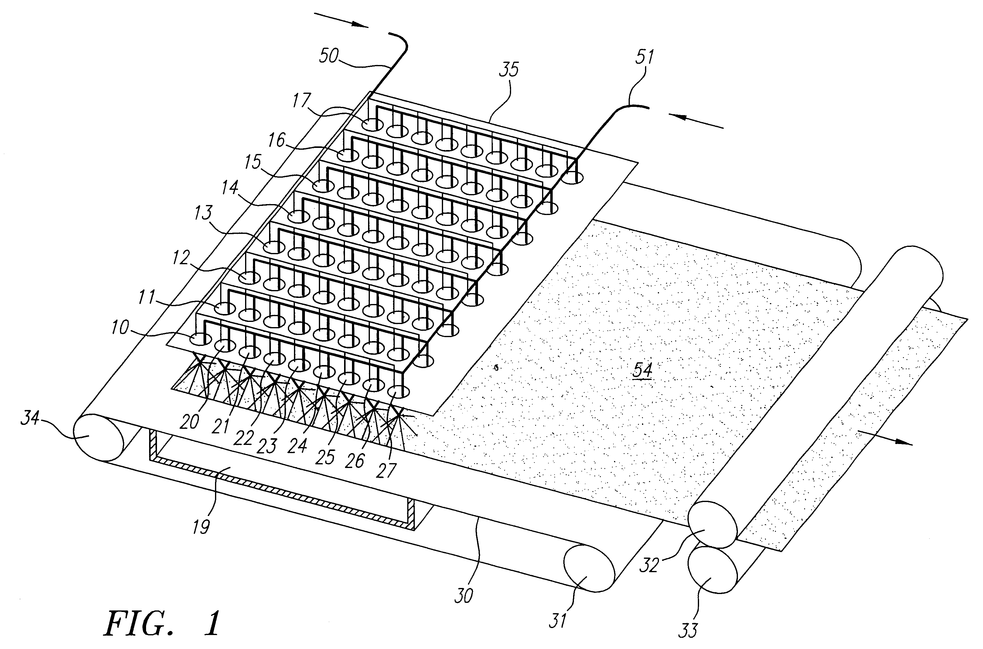
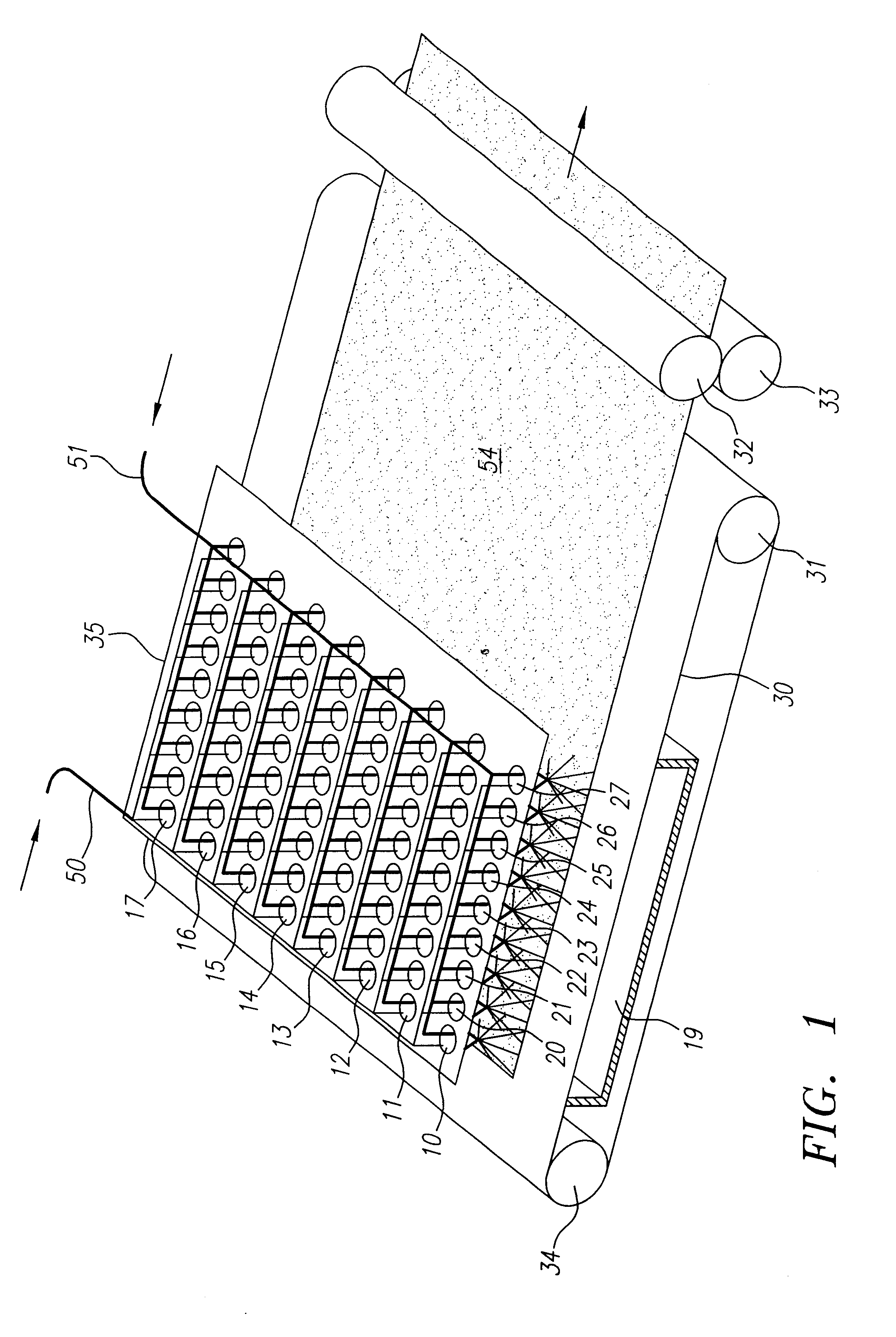
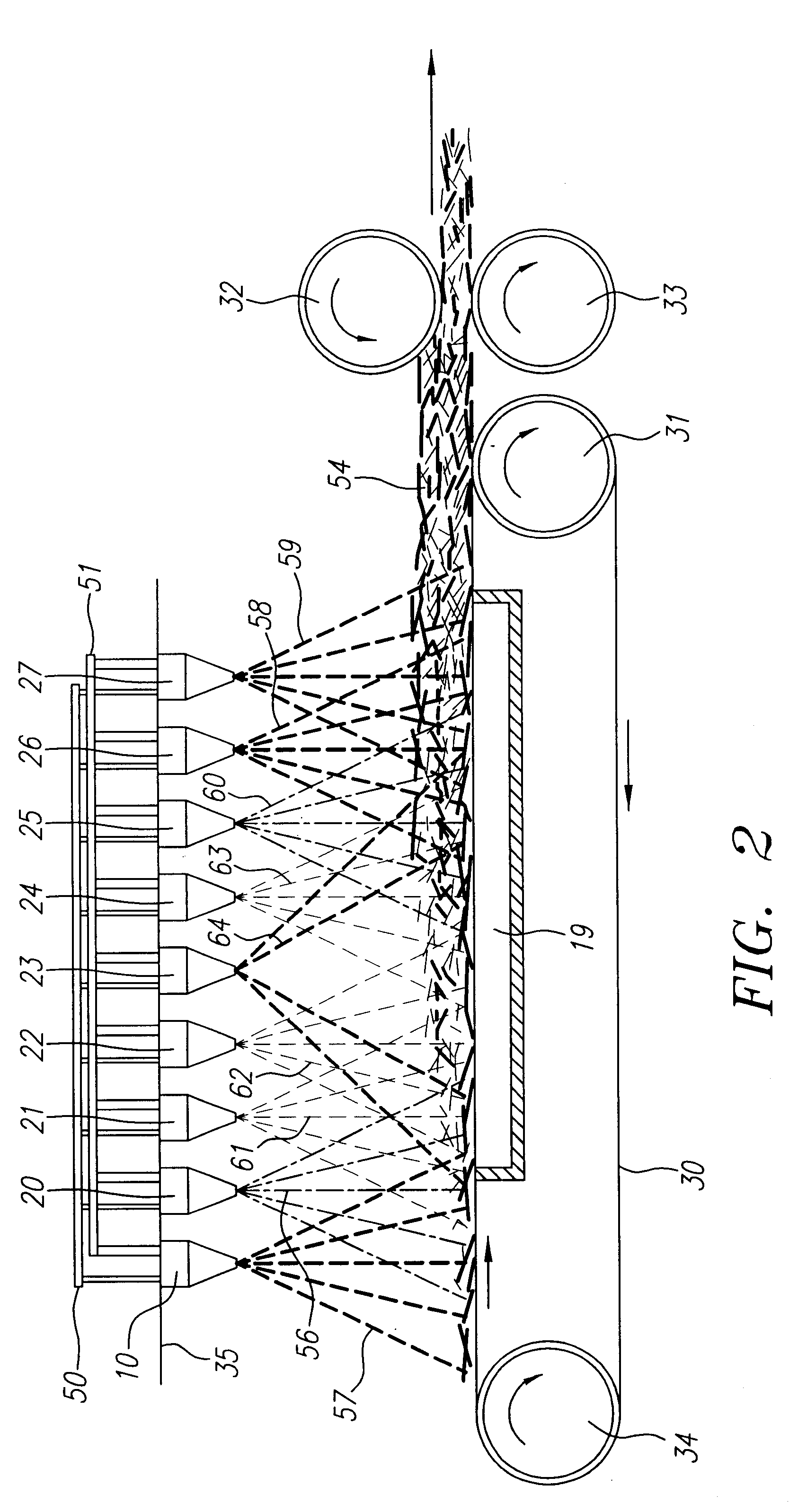
The vertical distance of the cell mounting plate 35 from the top surface of the foraminous belt 30 was found to be a factor affecting the filtration properties of the resulting fibrous web. At very short distances, the high momentum of collision and relatively high temperatures of the fibers contribute to their bonding together by fusion. As the distance is increased, the bonding tends to decrease and the loftiness of the resulting fibrous web tends to increase. Increasing loftiness generally decreases the overall resistance of the fibrous web to the passage of air, but with a corresponding decrease in filtration efficiency.
In preferred embodiments, the vertical distance could be from about 2 to about 16 inches, more preferably from about 4 to about 12 inches and yet more preferably from about 6 to about 10 inches. In further preferred embodiments, the vertical distance between selected cells in the array and the belt surface may be lower than other cells in the array, for example, to provide selected areas or patterns of less lofty, but higher bonded fibers in the web, or to provide a more uniform distribution of the more highly bonded fibers across the width of the web. For example, in one preferred embodiment, the cells in the first and second rows of the array may be arranged closer to the belt surface than the other cells in the array (for example, from about 2 inches to about 5 inches from the plane of the belt surface).

Problems solved by technology

However, most of these media lose efficiency rapidly or increase in price and investment and operating costs, as particle filtrate size decreases.
A major portion of such increased cost is due to costs associated with the increased resistance of the filter to air flow as the efficiency of particle removal is increased.
This creates a higher pressure drop for movement of air through the filter thereby imposing a greater work requirement upon the filter fan.
This, in turn, can require the use of larger and more costly fans which consume greater amounts of energy which can make the entire process economically prohibitive.
Also, filters capable of removing sub-micron diameter particles generally tend to rapidly plug up, necessitating frequent and costly filter replacement.
A number of significant problems, however, have inhibited the use appreciable quantities of sub-micron fibers in filter media.
For example, one problem has been the difficulty of achieving uniform deposition of sub-micron diameter polymeric fibers onto a collecting surface.
Further, the stray fibers can damage or impair the filter production equipment.
Another problem inhibiting the use of appreciable quantities of sub-micron diameter polymeric fibers in filter media results from the greater tendency of polymeric sub-micron diameter fibers to attach to each other in flight during formation, forming undesired loose clumps, "ropes" or other agglomerates.
The agglomeration problem is exacerbated by the presence of twisting and recirculating vortices in the ambient air which tend to twist the agglomerates into ropelike structures.
The agglomerates eventually settle onto the formed fiber web where they constitute a source of significant non-uniformity.
Another problem inhibiting the use of appreciable quantities of sub-micron diameter polymeric fibers in filter media results from the tendency of sub-micron diameter fibers to exhibit poor overall web mechanical properties and lack of self-support.
Sub-micron diameter fibers tend to only poorly attach to each other and are thereby susceptible to being lifted off and blown away by air currents associated with fiber production.
Also, when such fiber webs are used as air filters, significant quantities of the sub-micron fibers are carried away intermittently by the air being purified.
This results in unacceptable contamination of the air stream flowing through the filter.
Yet another problem retarding the use of sub-micron diameter polymeric fiber filtration media is the difficulty of uniformly distributing the ultra-fine fibers in the fiber web.
Moreover, because the higher surface area associated with each region of high concentrations of the sub-micron diameter fibers imparts to it a relatively high resistance to air flow compared to regions of low concentrations, the ultra-fine fibers in these regions tend to be bypassed by the air being filtered, thereby reducing their effectiveness.
In addition to non-uniform distribution over the length and width of the fiber web, there is also a tendency for the sub-micron diameter fibers to collect at a certain depth of the fiber web.
This results in premature plugging of the filter, since most of the solids separated by the filter collect in a thin plane.
However, experiences with asbestos fibers has led to concerns about the possibility of adverse health effects resulting from the inhalation of such fine glass fibers.
Also, pollutant-laden, used glass fiber filters cannot be disposed of by incineration.
They constitute a hazardous waste which must be handled, at considerable expense and risk, in land fills.
In response to these concerns, filtration media made from polymeric materials composed of fibers larger in diameter than their glass counterparts are displacing glass media, notwithstanding the poorer performance characteristics of the larger diameter polymer fibers.
However, Buntin further notes that very low melt viscosity and very high gas velocities are required to make even a small fraction of sub-micron diameter fibers.
Buntin reports that the required gas blast caused "extreme" fiber breakage and caused many fibers to be blown away from the laydown zone so that the fibers produced could not be incorporated into a practical fibrous web.
Further, the large amount of heated gas required in the process reported by Buntin tended to make melt-blowing uneconomical for sub-micron diameter fiber production.
(U.S. Pat. No. 5,207,970) report increased difficulty in obtaining webs having uniform properties as the blast air rates were increased.
In addition to uniformity, the melt-blowing processes do not have means to overcome the combined problems of web weakness, fiber agglomeration and tendency for detachment from the web inherently associated with sub-micron fibers.
The use of self-supporting porous layers of materials to overcome the inherent weakness of sub-micron fibers does not alleviated the problems of clumping, roping, segregation, and entrainment in stray air currents which occurs with sub-micron fibers prior to deposition on any surface.
Even when the combination has macroscopic good strength, the weak inner core of sub-micron fibers has been found to develop cracks and regions of separation in the vibration that occurs in certain filter uses, due to local weakness of the fiber-to-fiber bonds.
This allowed the air to be filtered to bypass or "short" through the filter, with a corresponding degradation of performance to an unacceptable level.
In addition, calendering with a pressure sufficient to cause fiber-to-fiber fusion and the use of bonding agents can tend to result in excessive degradation of filtration performance when applied to sub-micron fibers.
Where a binder is used, the high surface area of the sub-micron fibers causes them to soak up too much binder and become partially clogged.
Ahmed points out, however, that such arrangements lead to layers which are poorly attached to each other, unless the fiber bed thickness is considerably greater than the thickness required by filtration media.
Poor attachment of the structure forming layers to the layer of weak fibers would mean that the weak layer would be unprotected with respect to fibrous web tensile forces.
The poor attachment of the layers as one reduces fiber diameter results, in part, from the inability to space the conventional melt-blowing dies close to one another in the down stream direction.
This suggests that adaption of melt-blowing geometries for the commercial production of sub-micron diameter fibers would be prohibitively expensive both in operating and equipment costs.
It would be impractical to attempt to adapt this method to the production of intermixed fibers of sub-micron diameter fibers with fibers large enough in diameter to be reinforcing, since it would require the close spacing of blast jets with one or two orders of magnitude difference in velocity.
Also, the high blast velocities required to form sub-micron fibers tend to blow the bulk of the relatively large cellulose fibers away.
Binders in the form of particulates tend to plug filtration surfaces, however.
It would be difficult to adapt this procedure to sub-micron fibers since they would be in a clumped state upon collection prior to mixing, and the required uniformity of dispersion for an efficient filtration web would be difficult to establish.
While this method may be applicable to relatively large fibers, sub-micron fibers clump together when placed in contact with each other and it would be impractical to attempt to separate them after their collection and attempt to distribute them in a web containing larger fibers.
Also the gross inter-mixing of sub-micron fibers with the larger fibers can cause discontinuities in the bonds between the larger fibers so that the resulting web would be too weak for use as a practical filter medium.
Unfortunately solvent based processes are prohibitively expensive for general use.
In addition, the solvents can present the potential for pollution if they escape the enclosures of the process.
Unfortunately electrostatic charge may leak away during storage or use of polymeric fiber media made from relatively large diameter fibers.
Consequently, the interior volume of the filter may not be used efficiently, resulting in a relatively low dust holding capability.
None of these examples disclose practical methods for preparing commercial-sized sheets of composite fibrous webs of polymeric materials which contain significant quantities of uniformly distributed and attached sub-micron diameter fibers.

Method used


Image

  • Method and apparatus for producing high efficiency fibrous media incorporating discontinuous sub-micron diameter fibers, and web media formed thereby
  • Method and apparatus for producing high efficiency fibrous media incorporating discontinuous sub-micron diameter fibers, and web media formed thereby
  • Method and apparatus for producing high efficiency fibrous media incorporating discontinuous sub-micron diameter fibers, and web media formed thereby

Examples


example 2

A molten polypropylene polymer with a melt flow rating of 800 gram. / sec. was fed to an apparatus as shown FIGS. 1 and 2, except that the two dimensional array of fiber producing cells consisted of 9 rows spaced at 1 inch from each other in a downstream direction and each row contained 36 cells spaced one inch from each other in the transverse direction. The array of cells thereby constituted a 9.times.36 array.

The cells were adjusted to operate at a fiber production rate of approximately 0.3 lb. / hr. The cells of the first, third, sixth and ninth rows were set so that they produced fibers of approximately 1 to 2 microns in diameter. The cells of the remaining rows were set so that they produced fibers of approximately 0.1 to 0.8 microns in diameter.

The cell mounting plate was located 9 inches from the foraminous belt. The fibers produced by each cell generally collided with the cells produced by adjacent cells and settled in an intertwined state to form a fibrous composite fibrous we...


PUM

PropertyMeasurementUnit
diametersaaaaaaaaaa
diameteraaaaaaaaaa
diameteraaaaaaaaaa

Abstract

A composite filtration medium web of fibers containing a controlled dispersion of a mixture of sub-micron and greater than sub-micron diameter polymeric fibers is described. The filtration medium is made by a two dimensional array of cells, each of which produces a single high velocity two-phase solids-gas jet of discontinuous fibers entrained in air. The cells are arranged so that the individual jets are induced to collide in flight with neighboring jets in their region of fiber formation, to cause the individual nascent fibers of adjacent jets to deform and become entangled with and partially wrap around each other at high velocity and in a localized fine scale manner before they have had an opportunity to cool to a relatively rigid state. The cells are individually adjusted to control the mean diameters, lengths and trajectories of the fibers they produce. Certain cells are adjusted to generate a significant percentage of fibers having diameters less than one micron diameter, and which are relatively shorter in length and certain other cells are adjusted to generate a significant percentage of structure-forming reinforcing fibers having diameters greater than one micron diameter which are relatively longer in length. By employing appropriate close positioning and orientation of the cells in the array, the sub-micron fibers are caused to promptly entangle with and partially wrap around the larger reinforcing fibers. The larger fibers thereby trap and immobilize the sub-micron diameter fibers in the region of formation, to minimize the tendency of sub-micron diameter fibers to clump, agglomerate, or rope together in flight. Also, the larger fibers in flight are made to form a protective curtain to prevent the sub-micron fibers from being carried off by stray air currents.

Description

The present invention relates generally to methods and apparatuses for producing fibrous media, and fibrous web material formed thereby, and in preferred embodiments, to methods and apparatuses for producing composite fibrous media composed of discontinuous fine fibers and controlled dispersions of discontinuous ultra-fine or sub-micron electrostatically charged or uncharged fibers. Further preferred embodiments relate to filtration media and absorbent media comprising such composite fibrous media.The increased recognition of the deleterious health effects of chemical and biological pollutants, which often are in the form of particles of less than one micron in diameter, has created an urgent requirement for filtration media capable of removing such particles in an efficient and economical manner. There is a wide range of filter media available for removal of particles from air used for breathing or other processes requiring specific air purity standards. However, most of these medi...

Claims


Application Information

Patent Timeline
Patent Type & Authority Patents(United States)
IPC IPC(8): B01D39/16D04H5/00D04H5/02D04H1/54D04H1/46B29C48/345D04H1/56D04H1/72
CPCB01D39/1623D01D5/0985D04H1/465D04H1/54D04H1/72D04H5/02Y10S55/05D04H1/492D04H18/04D04H1/43835D04H1/43838
Inventor TOROBIN, LEONARDFINDLOW, RICHARD C.
Owner THE PROCTER & GAMBLE COMPANY
Why Eureka
Try Eureka